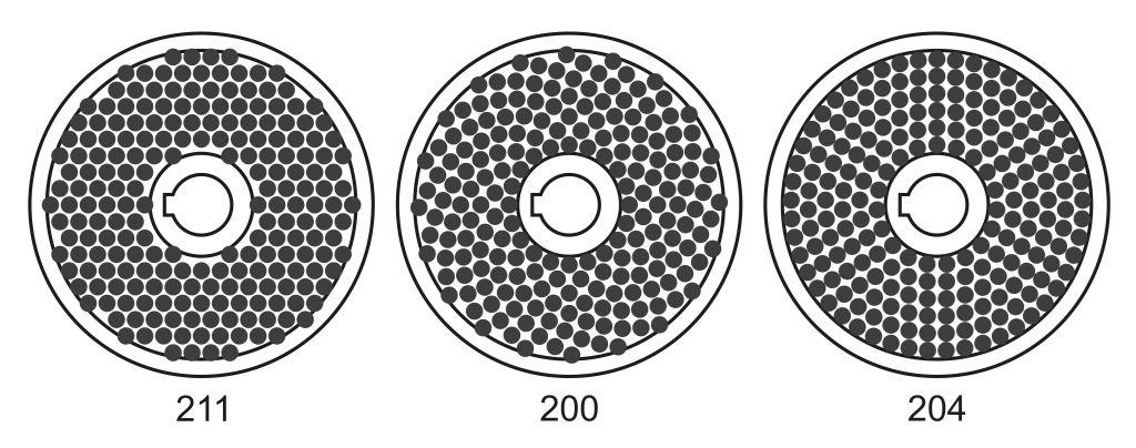
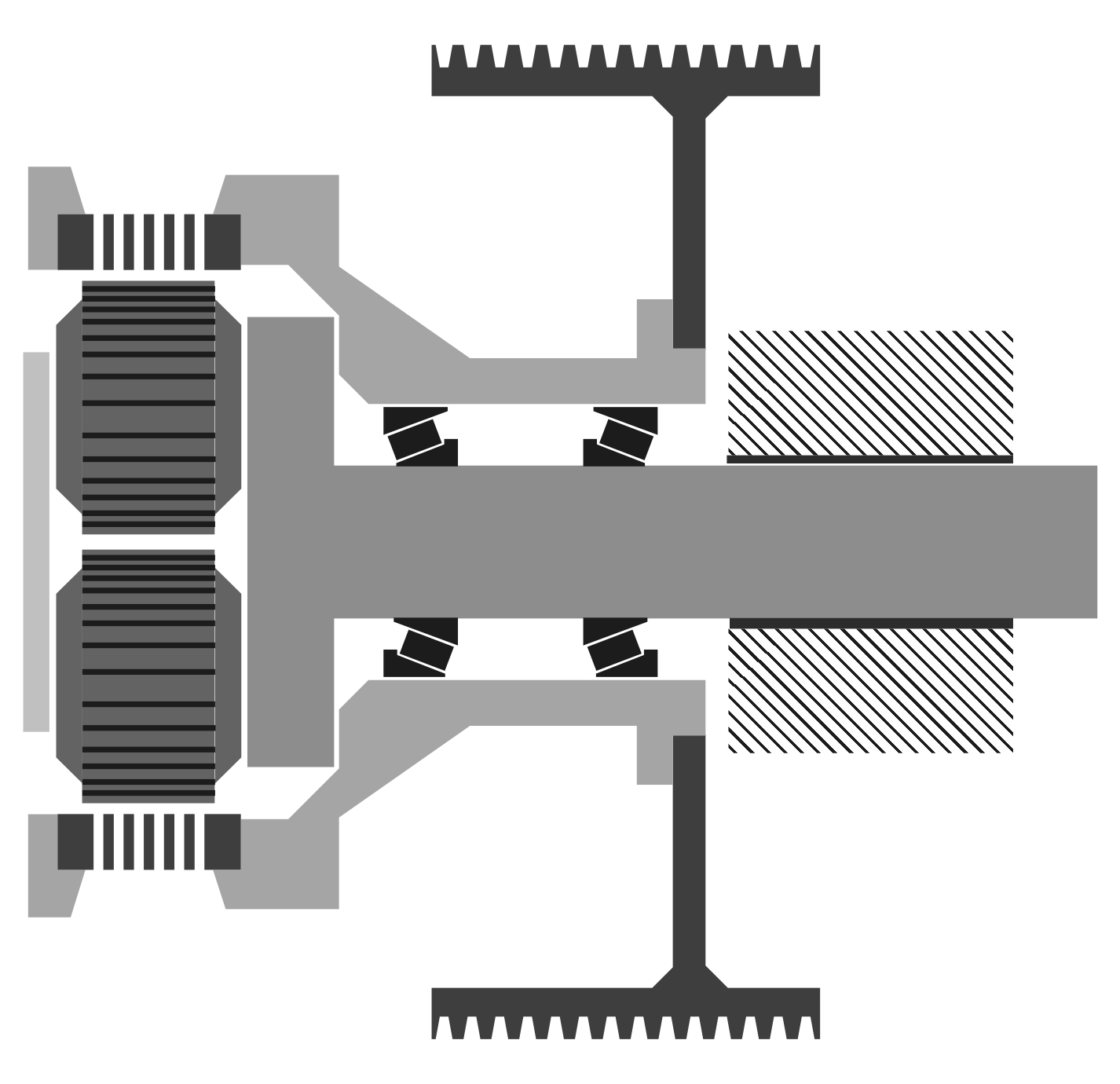
 When it comes to gear-driven pellet mills, giants like American CPM and German Kahl are often the global leaders. However, in the realm of belt drive pellet mills, pioneers and models to emulate are the Muench RMP units. The difference in construction lies not only in the type of drive but also in the load distribution principles. In a gear-driven pellet mill, the frame serves as the core of the entire unit. In contrast, a belt-driven pellet mill features a compression assembly, a large pulley, and a platen all mounted on a relatively thick stationary shaft, creating a cantilever load. The stationary shaft is tightly fitted into the striated frame, as indicated in the drawing. It can still rotate if excessive force is applied. If there is an emergency impact load, the stationary shaft will rotate, breaking a safety shear pin, and powering down the motors. These types of pellet mills often use pneumatic overload protection, automatically opening a bypass for material around the die. Considering the possibility of belt slippage on the pulleys, three types of overload protection are used depending on the nature of the emergency.
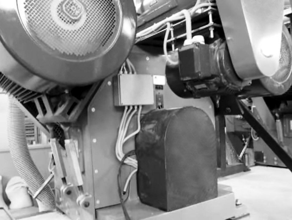
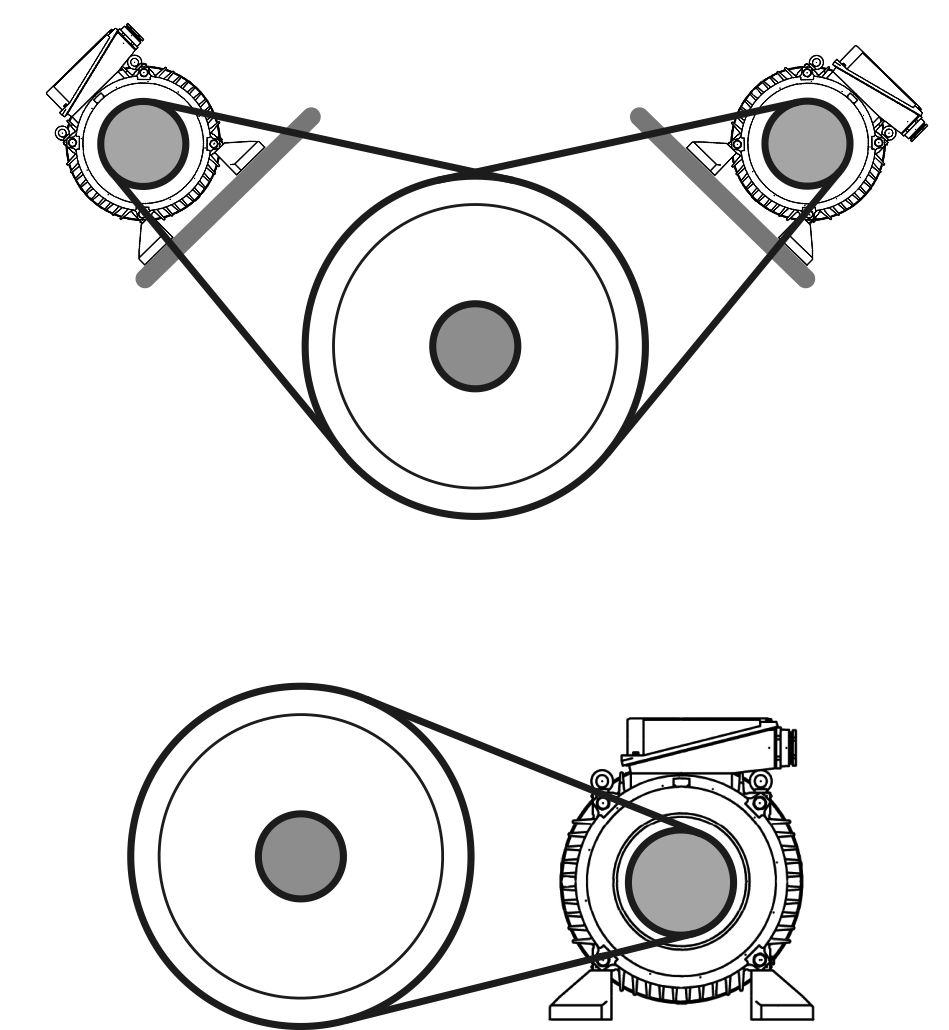 There is little benefit from the cantilever load on the stationary shaft, so German engineers devised a solution by placing two motors above the main pulley. This design uses the belt tension to offset the weight of the entire compression unit assembly. On one hand, this configuration complicates the frame design and maintenance. On the other, distributing the load across two drives significantly reduces vibrations and allows for optimal pulley diameters to match motor speeds. The motors themselves are reinforced with much stronger front bearings equipped with force lubrication and temperature sensors. Many manufacturers opted for a simpler approach by placing one motor to the side of the compression unit. This simplified the structure and eased maintenance but increased the already significant radial load on the drive pulley of the motor.
 At first glance, a belt drive for small capacities seems simple. However, there are numerous nuances in its operation when transmitting maximum power. Engineers often focus on the smaller pulley, because the limit of force transmission from the motor to the pressing unit is reached here due to the smaller belt wrap and contact area. The lowest speed serial motor rotates at around 700 rpm, so the difference in diameters between the driving and driven pulleys must be 3-4 times, which is considerable, and it is impossible to use more high-speed and cheaper motors with the same power. If the driven pulley has a diameter of 1.2 meters (4 feet), the driving one should be about 300 mm (12 inches), ideally taking the minimum standard diameter for the belt section of 315 mm (13 inches). With a resulting linear speed of around 12 m/s (39 ft/s), one belt of this section transmits 9 kW of power nominally. Hence, for a 90 kW pellet mill, two 45 kW motors should be used, each with a pulley accommodating five belt grooves. Catalogs of pulley suppliers show that 2-4 grooves are common, which is no coincidence. Further increasing the number of belts leads to critical load on the motor shaft, either causing insufficient tension and reduced power transmission or overload and premature bearing replacement. From the motor's torque and the pulley diameter, the force exerted on the belts is around 4000 N nominally, doubling during motor overload. Add 140 N tension force per belt, approaching the radial load limit for this motor of 9000 N. Given the nature of the load during pelletizing, calculations are close to nominal with little strength reserve for short-term or impact loads.
From such calculation conditions and operational experience on brand-name pellet mills, the following provisions are made:
- Reinforced motor bearings
- Belt slip sensors
- Sealed belt protection from dust or air flow into the housing through filters
- High-quality cast iron pulleys with ground contact surfaces
In such a configuration, the cost increases significantly from the initial price. The only way to reduce radial load is to increase the driving pulley's diameter. However, reducing motor speed is not an option, and the already large driven pulley becomes even bigger and costlier. Increasing the gear ratio by downsizing the belts is possible, but significantly extending the driving pulley to 8-10 grooves creates additional cantilever and radial load without solving the issue.
Generally, a well-refined German design, with adequate maintenance and operational conditions of all protections and automation, serves quite stably and predictably. However, with unskilled personnel and improper raw material preparation, unexpected, lengthy, and costly repairs can spoil the situation. Disabling slip sensors might cause one edge of the pulley to overheat, and temperature differences can easily lead to cracking on the second groove from the edge, rendering the part unusable with a 2-3 month wait for its replacement. Excessive belt tension to compensate for uneven wear from malfunctioning sensors sometimes results in fatigue failure of the motor shaft. A single belt break in an enclosed space typically damages the entire set, so several dozen belts should be kept in reserve. Occasionally, people remove covers to mitigate these losses, protecting belts but creating a hazard for personnel. It should also be noted that using "similar" belts with a different angle damages pulleys and wears out even original consumables quickly thereafter.
When a single engine is mounted on the side, the situation with radial load and power transmission becomes more complicated. However, depending on the country of manufacture and the availability of consumables, a two-stage transmission is sometimes used. The second stage often has a toothed belt drive with a gear ratio of 1:4. Intermediate shafts are placed above the pressing unit to relieve the cantilever load from the stationary shaft, and the engines are installed at floor level or, as in the German version, with the fans turned towards the door.
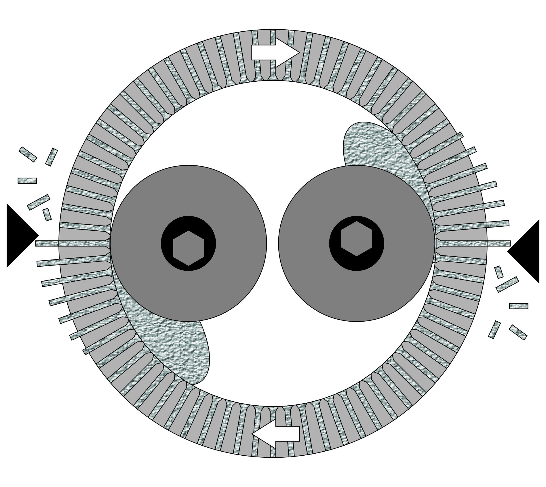
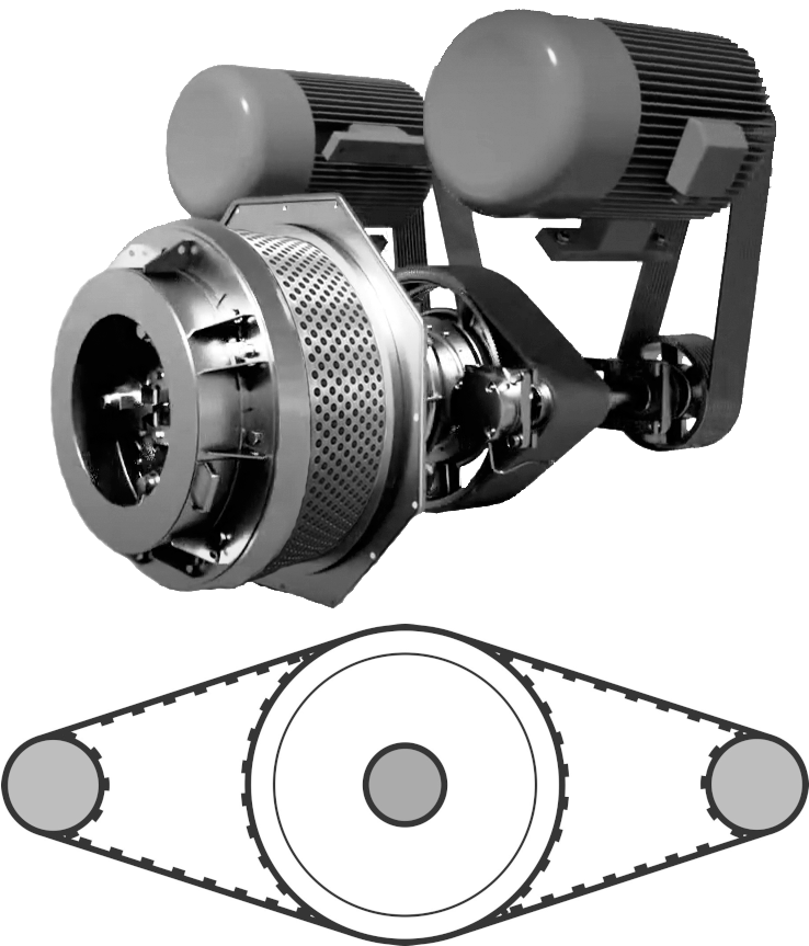 The most successful arrangement is shown in the image: intermediate shafts lie in a horizontal plane with the pressing unit. This allows the same belt to be used twice per rotation, reducing the necessary width of the main toothed pulley, and due to its compactness and light structure, reduces the cantilever load. There is a vast choice for the toothed belt regarding its width and tooth size, but it's best to stick with the most popular widths such as 50 mm, 100 mm, or 150 mm (2, 4, or 6 inches). For the most powerful drives, up to six toothed belts with widths of 100 mm or 150 mm (4 or 6 inches) are used. The driven pulley is designed for a single belt, while the driving pulleys have flanges and are mounted on intermediate shafts. This setup creates more hustle in maintenance but moves the structure away from critical loads and generally increases the operational time before failure. In terms of the number of bearings, the unit already surpasses the gearbox version, with the only difference being the use of pulleys instead of gears, and the bearings are lubricated not from a common bath.
At first glance, the presence of intermediate shafts might seem odd. However, directly driving the toothed transmission with engines is not only hazardous for their bearings but also expensive. Reducing the revolutions by half in the first stage also approximately halves the cost of engines while maintaining power. Moreover, this design allows relatively primitive technologies to be used to create the most powerful pellet mills. If, for a gearbox pellet mill, the acceptable limit for series engines is 355 kW (476 hp), then samples with a two-stage belt transmission occupy the market segment with total power from 220 to 500 kW (295 to 670 hp) without the need for developing special gearboxes and complex to manufacture forgings. Thus, this approach allows the creation of pellet equipment giants using simple methods with sufficient reliability and low cost, and a short production cycle.