Due to its simple design, minimal strength calculations, and versatility, this is the most common type of dryer for bulk mineral materials and biomass. It typically consists of a horizontally positioned barrel supported by rollers for free rotation. At one end, a hot air agent is introduced along with moist materials; at the other end, dry material and a steam-hot air mixture exit. In the inlet section, there are steel strips forming a ladder, allowing the hot air agent to pass through and carry away lumps of sawdust and other biomass. Without this feature, piles of wet material would likely accumulate, leading to overheating and possible ignition.
 In the drum, shifting in the flow is often combined with other means of movement. An inclined setup prevents the accumulation of stones, which are not always expelled by the flow of materials. Curved spiral blades in the first meter of the drum facilitate rapid distribution of the loaded materials. In triple-pass drums, pneumatic conveying prevails in narrow sections.
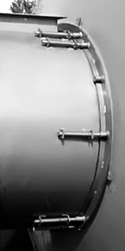
Sealing between the moving drum flange and stationary pipes is achieved in three popular ways:
- Contact seal with lubrication applied to the drum flange
- Contact seal without lubrication, using various polymer materials
- Labyrinth seal
The labyrinth seal is typically used at the drum's entry point, where the highest temperatures occur, leading to the rapid drying of graphite lubrication and damage to polymer flaps. Additional rollers are placed on this side to prevent the band from longitudinal displacement and protect the labyrinth seal from damage. High alignment requirements during installation and the risk of displacement due to vibration during drum operation have made this type of seal unpopular for the mass production of inexpensive dryers.
 The contact seal with lubrication is universal for both ends of the drum. Loops are welded around the pipe in two rows, between which springs are placed. Smooth rods, with pre-drilled holes for locking pins, pass through the loops and springs, pressing against one end of the spring through a washer. This design allows the pins to move, compensating for the drum's expansion when heated.
The pins press against flange catchers—welded pieces of standard steel pipe around the circumference. The flange itself is made with an internal diameter 1-2 mm larger than the pipe for ease of installation, and air suction through this gap is insignificant. Since the pipe diameter is typically 20-30 mm smaller than the drum hole for easier alignment matching, the sliding flange effectively covers this space. This area is usually lubricated with graphite grease, and the flanges serve as a consumable part with a replacement interval of 1-3 years, depending on their thickness and the combined force of the springs.
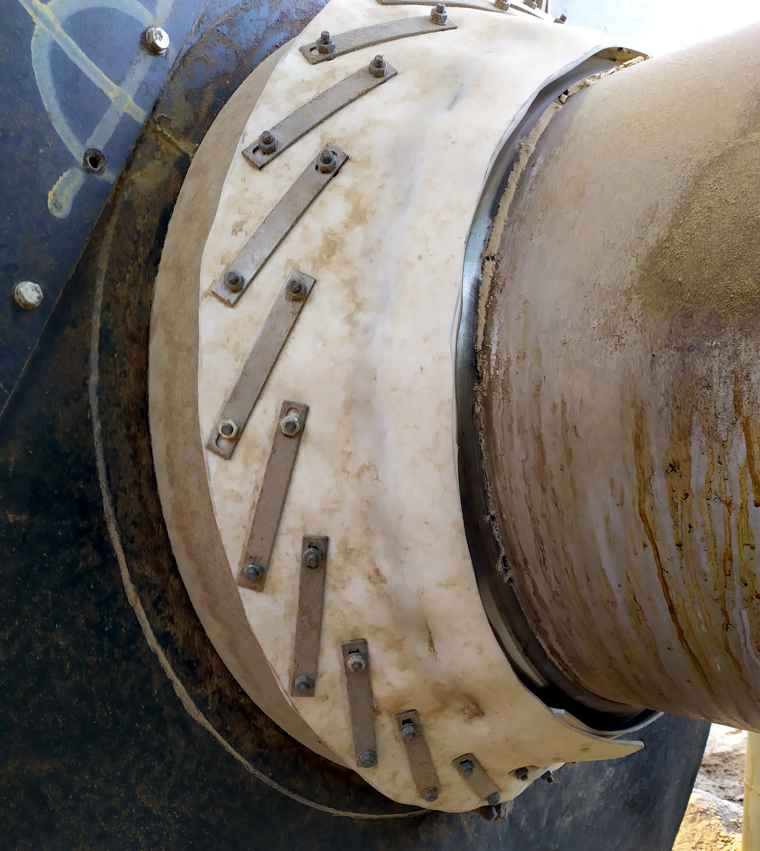 A dry contact seal, also known as a petal seal, is made using various polymer plates that are wear-resistant yet flexible. Materials such as silicone, polyurethane, rubber, PTFE, among others, are suitable for this. Conical flanges with different taper angles are welded to the drum outlet and pipe. The pipe flange is two to three times narrower on the side, leaving much of the drum flange exposed. This difference in taper creates a bend at the transition point, ensuring stable contact between the soft seal and the stationary pipe. Around the circumference of this exposed part of the drum flange, two to six polymer plates are tightly attached, which snugly fit around the pipe flange. The vacuum in the drying system helps press the petals against the flange, providing self-sealing, yet it is not strong enough to cause excessive friction and tear the polymers. Silicone plates are typically 4-5 mm (0.16-0.20 inches) thick, PTFE plates around 2 mm (0.08 inches), and rubber plates 3-5 mm (0.12-0.20 inches) depending on rigidity.
 Drums can be driven in various ways. A common feature is the attachment of two rails on the drum's exterior, also referred to as tires. Their width ranges from 50 to 200 mm (2 to 8 inches). These tires rest on four rollers, with two on each support station, and often, two additional rollers are provided on one side to limit the drum's longitudinal movement. For smaller drums, solid rubber-coated wheels from warehouse forklifts are used as support rollers due to their longevity in terms of wear. When solid steel support rollers are used, flanges at the edges, each 10-15% of the total wheel width, restrict axial drum movement. One support station uses rollers with two flanges, while another uses one flange positioned towards the drum's center, allowing the tire to shift to the edge of the support when the drum body expands from heat.
The most common way to rotate the drum is by connecting a motor reducer to two or four support rollers. Although this is a simple solution, if the drum is overloaded with material or if contaminants settle on the rollers, they may begin to slip, halting the drum's rotation. In such cases, the top layer of material can overheat and ignite if the safety mechanism does not act promptly on a temperature rise. A more reliable and cost-effective method is a chain drive between the motor reducer and a sprocket gear ring mounted on the drum. The gear ring can be made using CNC plasma cutting without hardening, as the load is distributed across many teeth and the chain speed is very low. The main drawback is that even a slightly elongated chain can easily slip off large sprockets. The finer the chain pitch, the more significant the mismatch between links and teeth, which is slightly mitigated by an "improperly" manufactured ring with "thin" and relatively short teeth, allowing some link displacement. The third method, the most expensive yet the most reliable, is attaching a gear to one of the tires with a matching gear on the drive. Due to size considerations, the drum gear is usually manufactured from several segments, cut with an abrasive water jet from pre-hardened blanks. The gear teeth are made as large as possible, and the drive utilizes a coupling with damping properties. This setup ensures smooth and highly reliable operation.
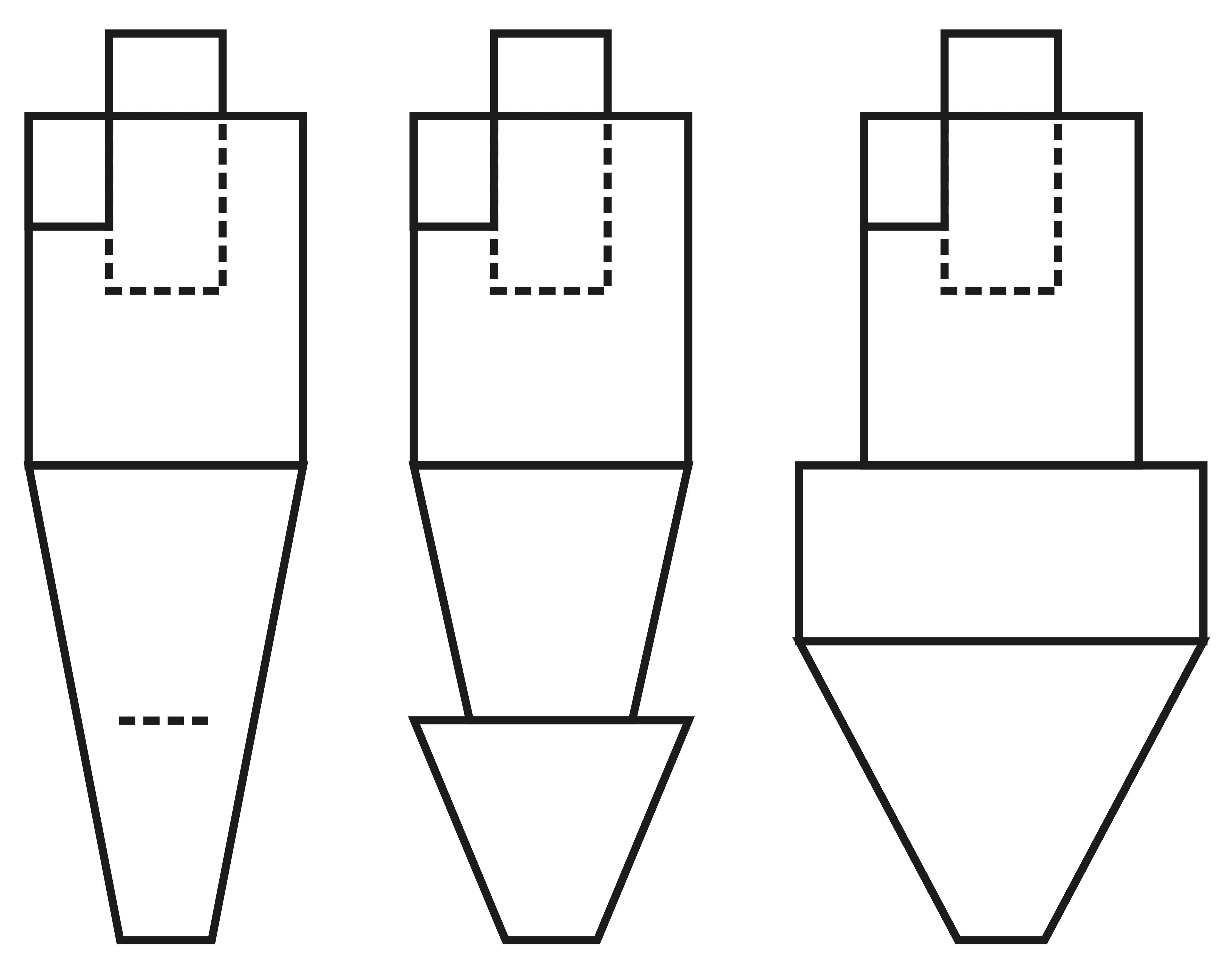
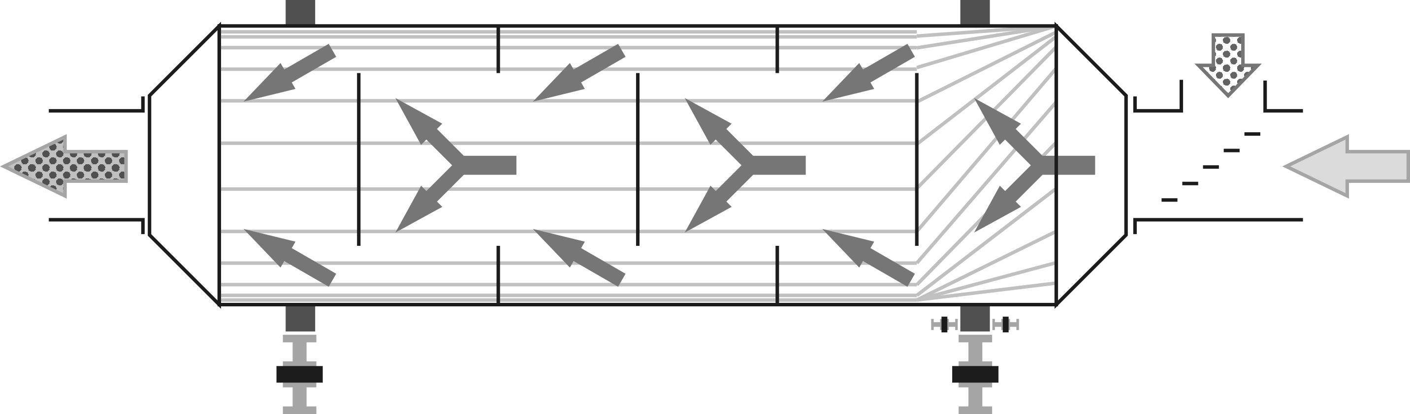
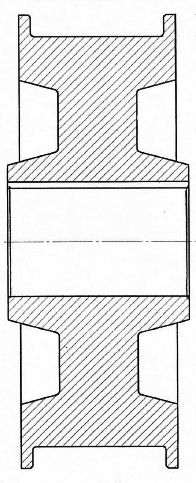
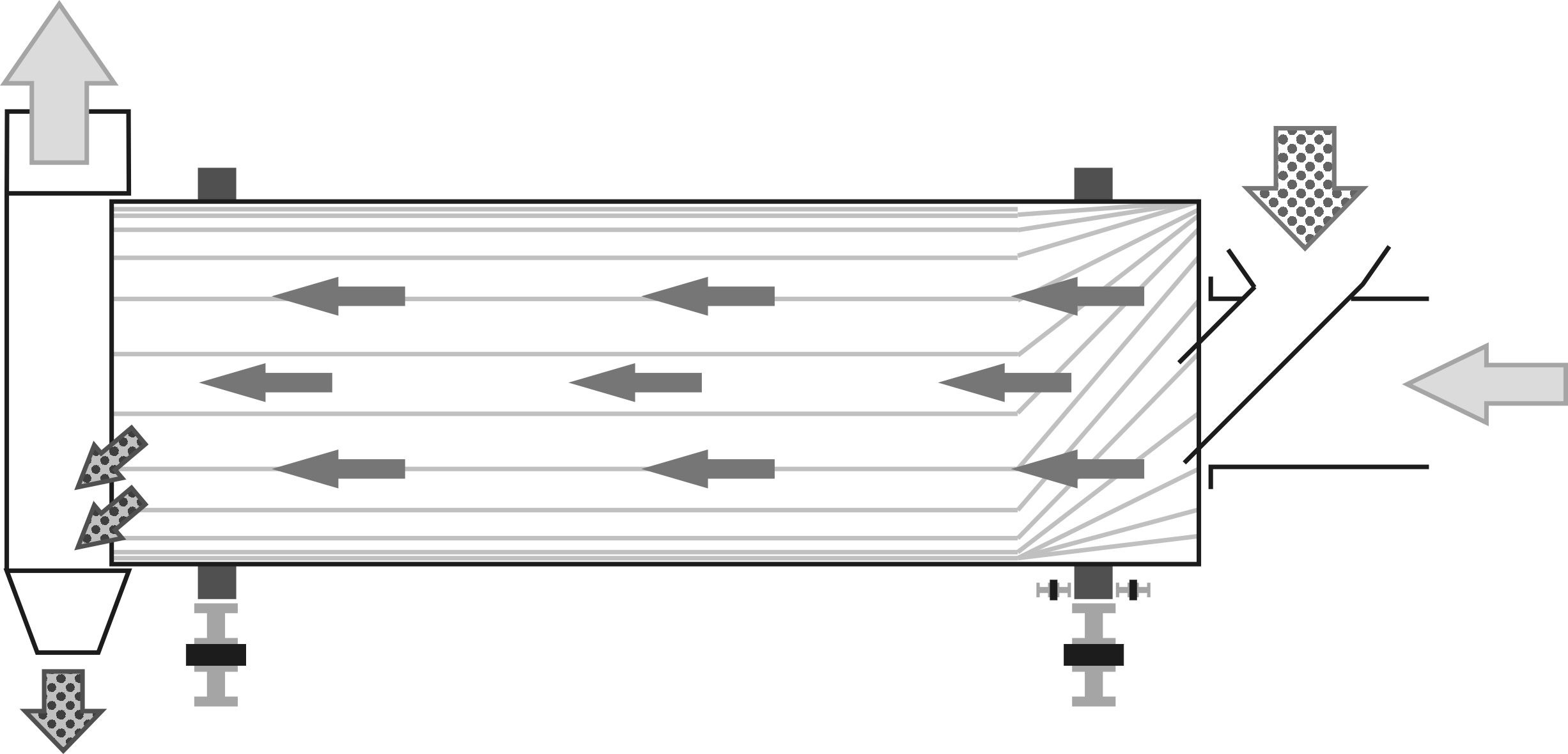
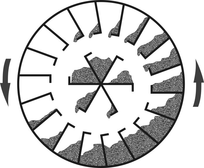 The internal surface of the drum is lined with blades and baffles designed to lift the raw material as high as possible before allowing it to fall into the flow of the heat agent. This internal setup is referred to as the fittings, which vary significantly depending on the density and moisture content of the material and their positioning along the dryer. At the start of the dryer, the material is primarily heated to 60-70°C (140-158°F), while in the rest of the dryer evaporation becomes more active, preventing the material from overheating. As you can see from the directions of the heat agent flows, several partitions are installed across the drum. These include alternating walls with circular cutouts in the middle and separate circles of the same diameter as the cutouts. These partitions help retain the material in the drum and mix the gases more thoroughly. Geometric calculations indicate that to achieve the same cross-sectional area for the cutouts in the partitions and the gap area around the transverse circles, the diameter of the holes and circles should be 70% of the drum’s diameter. However, considering partial blocking by the material, it is optimal to approach the "golden ratio" of 62% by aligning the bent edges of the blades with the partition edges. Increasing the number of partitions noticeably boosts the drum's specific productivity per cubic meter of working volume, but simultaneously raises aerodynamic resistance to the flow. In practice, the vacuum in most observed drum dryers is several times lower than the nominal capacity of the fan extracting gases from it. Before optimizing the design concerning partitions and resistance, the entire dryer system must be calculated, including cyclones and air ducts, to ensure it can withstand high vacuum without collapsing.
The understanding of the thickness, shape, and quantity of the fittings begins primarily with their resistance to complete blockage by material forming "dead" zones, reducing the dryer’s effective working volume. Secondly, the spacing of the blades and the size of the bent shelf is checked. Increasing the spacing and shelf size aids in better weight distribution of the material and reduces the load on the rotation drive, but decreases productivity due to a smaller contact area between the material and the fittings’ surface. In a properly designed biomass drying drum, productivity reaches 1 ton per hour for every 15-20 m³ of working volume.
 The thickness of the sheet metal for making the fittings is usually 5mm (0.2 inches). With a thinner material, rigidity and resistance to impacts from bricks or hardened lumps drastically decrease, but using a thickness of 2-3mm (0.08-0.12 inches) can reduce the drum’s weight up to 30%. A thickness of 10mm (0.4 inches) and more is used for drying sand, where wear resistance and the ability to quickly replace worn out fittings become a priority. The distinction between drying drums for minerals and biomass is not only in the thickness of the fittings. The drying principle differs significantly: sand dries from the surface and must cover as long a trajectory in the flow as possible, whereas organic material heats more effectively through contact with the hot metal, so it spends most of the time resting on the fittings.
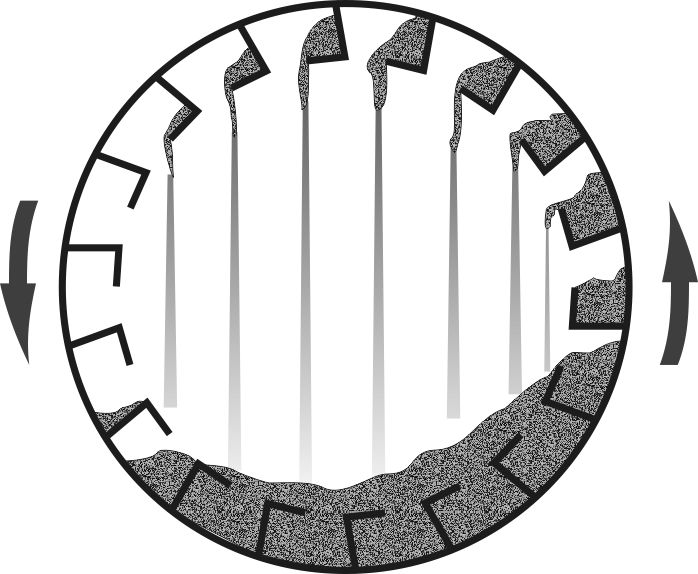
 In sand drum dryers, the fittings are located only on the inner surface and are relatively narrow. A much greater volume of air is passed through the free space in the center due to the weak ability of sand grains to float. The main mass is discharged mechanically through the edge, leaving the cyclone with only fine dust particles. When attempting to dry fresh sawdust with natural moisture in such a drum, it is necessary to significantly reduce the flow of the heat agent. Even at the maximum inlet temperature, undried material is carried away due to the strong airflow. This reduction in flow automatically decreases the heat flow, or thermal power of the installation, which cannot be compensated by increasing the inlet temperature. This is because the carried-away undried material is also accompanied by high outlet temperatures, resulting in extremely low heat exchange efficiency, even at minimal rotation speeds.
A piece of steel sheet heated to 200-300°C (392-572°F) cools at a rate of 30-50°C (54-90°F) per second when submerged in biomass. This is the reason most drum dryers and similar devices for drying sawdust complete half a rotation in 4-5 seconds, with a nominal rotation speed of 6-8 revolutions per minute. This is sufficient for the fittings to cool within the mass, like an iron driving water out of a wet cloth. Notably, the steam being expelled passes through the sawdust layer, warming it up. For the next 4-6 seconds, the fittings are exposed to the blowing heat agent, regaining temperature. This is, of course, not the only method of heat exchange; some heat is transferred directly to the floating particles. The exact proportion is determined by the fraction size. Fine sawdust from a band sawmill lays in a dense mass with a large contact area, favoring contact heat transfer. It floats well, so at higher rotation speeds, it is easily carried away undried. Crushed chips, on the other hand, have little contact with the surface and need frequent mixing to heat uniformly, presenting different sides to the fittings. The denser larger particles are less prone to floating, allowing for more vigorous mixing; thus, the drum can rotate at much higher speeds without ejecting undried material.
Several dryers were tested on different fractions for this reason. In one scenario, the pelletizing line alternated 2-3 shifts on crushed chips and 1-2 shifts on fine sawdust. The maximum temperature difference between inlet and outlet was achieved at 5 RPM for sawdust and 12 RPM for crushed chips under the same settings for the amount and temperature of the heat agent. The productivity for crushed chips was 20-25% lower, which was anticipated. Attempting to dry chips at 5 RPM reduced productivity by 60%, and the dryer was constantly on the verge of triggering an emergency shutdown due to exceeding outlet temperatures, creating a fire hazard.
As shown earlier, the rotation speed of the drum primarily affects the material's residence time within it. Typically, the material reaches the desired moisture level well before it reaches the outlet chute. The last 20-30% of the drum's length essentially does not contribute to drying but rather holds the material before unloading. Continuously adjusting the drum's rotation for specific material, weather, and temperature from the heat generator can lead to errors and produce low-quality pellets. However, leaving unused drum volume serves no purpose and is wasteful. The simplest solution for material with uniform particle size and varying moisture and temperature is to link the feed drive frequency to the drum's rotation speed using an adjustable coefficient. If the material is partially dry, an increased feed rate will help maintain output temperature, while accelerated rotation will lead to quick throughput and rapid drying. When sawdust with snow is encountered, which needs extended contact with hot surfaces, the feed rate decreases due to a drop in output temperature, and slowing the drum enhances the heat exchange intensity. For excessively wet sawdust, performance might drop by 20-30%, although with 70-75% moisture, productivity typically halves without triggering emergency shutdowns from temperature overages.
The ratio between the feed rate and drum rotation speed can be adjusted individually for each type of material: sawdust, crushed chips, or green chaff. To switch to a different type without halting production, the operator simply selects the material type from the menu, allowing the dryer to continue delivering optimal output. The economic benefits from this increased productivity can offset the automation installation costs within a few days of operation.