 To ensure a smooth supply of raw materials to crushers and pellet mills, so-called damper bins with dispensers are used. They are usually equipped with an agitator to break up arches, with the agitator blades passing very close to the outlet, to which an auger or chain conveyor is attached. The distance from any part of the agitator to any wall should be at least 50 mm (2 inches) so that even with fibrous materials, there is no jamming from clumps gathered in front of the blades. The volume of such bins is selected with the consideration that the feeding unit can be stopped for inspection or adjustment without causing overflow. For sawdust, the working volume is usually 1-2 m³ (35-70 ft³), and for additives from 40 to 200 liters (10-53 gallons). The most common designs are with a vertical or horizontal axis of mixer rotation. Vertical bins are suitable for grain mixtures because the agitator is near the bottom and works under the pressure of the entire mass of raw materials. Originally, such a bin is designed not just for feed mixtures, but specifically with a grain content of at least 80%. In crushers, screens of 6-8 mm (0.2-0.3 inches) are used, producing a crumble whose flow properties are similar to grain. This is the cheapest solution with narrow specialization. When fibrous or clumpy raw material enters, the load sharply increases, self-compaction occurs, and stops happen. As a result, when translating equipment from feed purposes to biofuel, the permissible filling volume of the bin sharply decreases, complicating operation and causing frequent stoppages of the entire line.
Developing an agitator for such an apparatus is an art in itself, as it must be simultaneously slender to reduce resistance and thick enough to handle high loads. With a bin diameter of 1.8 meters (5.9 feet), the maximum power of the worm gearbox is 5.5 kW (7.4 hp), which is insufficient for fibrous material. Switching to a cylindrical gearbox definitely helps solve the problem and even allows for building rather tall bins with an increased volume up to 5 m³ (177 ft³), but it noticeably increases the cost of the construction.
Challenges also occur with sealing the shaft exit from the bin, as the raw material creates pressure at the bottom with high abrasiveness, leading to seal damage, entry into bearings, and the drive. For chip feeding, seals are usually not made, leaving a minimal gap between the housing and the shaft. However, for flour feeding into a pellet mill, this setup has very low reliability. A thick felt gasket trapped between the agitator plane and the housing somewhat relieves the situation. The cost of its damage is the replacement of the motor-reducer.
The presence of a drive under the bin imposes restrictions on the size of the exit window, which can lead to pulse feeding in sync with the rotation of the agitator when reaching maximum productivity. This happens because the dispenser manages to take the material, while new material has not yet fallen through the window onto the conveyor. Partially solving the problem involves mounting the drive on the bin lid, with a shaft catcher attached at the bottom acting as a sleeve where the lubricant is the raw material itself. The clearance between the shaft and sleeve is left at 5-10 mm (0.2-0.4 inches) with holes in the cylindrical part for free circulation of raw material, otherwise, overheating and ignition are possible.
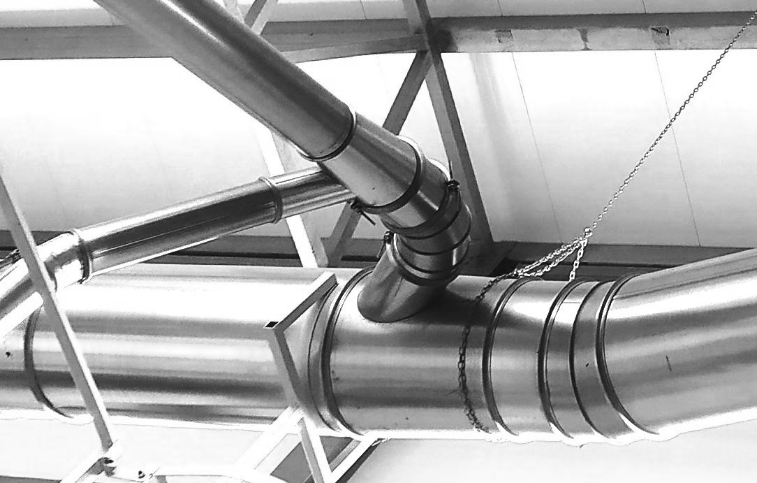
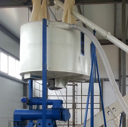
In the photo, you can see another technological error: using the cylindrical shape of the hopper, raw material is fed into it by pneumatic transport through a hose from the crusher tangentially to the wall. The idea is for the material to settle while the excess air exits through woven filters. This somewhat works with coarse material, but when feeding sawdust, the filters quickly become clogged with the bulk of the wood dust, creating excess pressure. When the material level in the hopper drops to a minimum, the excess air suddenly blows through the feeder, uncontrollably filling the pellet mill’s pressing unit. This leads to a sudden overload, and in case of a weak construction and lack of proper protection, can cause damage to the expensive equipment. Although installing a cyclone with a sluice for proper material settling doubles the cost of the damper hopper, it pays off in safety in just the first few months of operation.
Even more dangerous is the assembly of the hopper with filters on the lid in terms of fire risk. If a nut enters the crusher during the processing of dry shavings or sawdust, the flame from the air duct goes directly into the hopper, where the shavings swirl around. The filters burn out in seconds, and the rising vortex of fire turns the hopper into an inverted rocket with four nozzles.
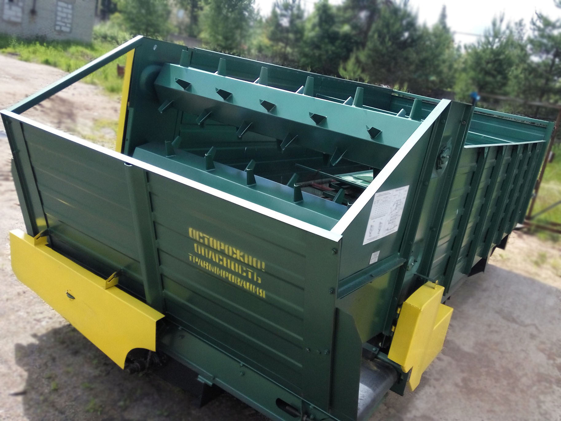
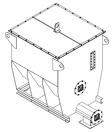 It is much more effective to use hoppers with a horizontal stirrer. The mixer shaft is mounted on two bearings installed in the vertical walls. The material reaches them only occasionally, so the seals last very long. There is enough space outside to install a chain sprocket with a diameter of 0.7-1 meter (2.3-3.3 feet), allowing the use of a cheap 1.5-2.2 kW (2-3 hp) worm gear reducer with a pre-installed sprocket diameter of 150-200 mm (6-8 inches). This way, a high torque is created in a fairly cheap manner, and considering the relatively low chain speed, the chain transmission can last 5-7 years with timely maintenance. This layout is taken from a feed mixer, where the mixing intensity and drive power are an order of magnitude higher.
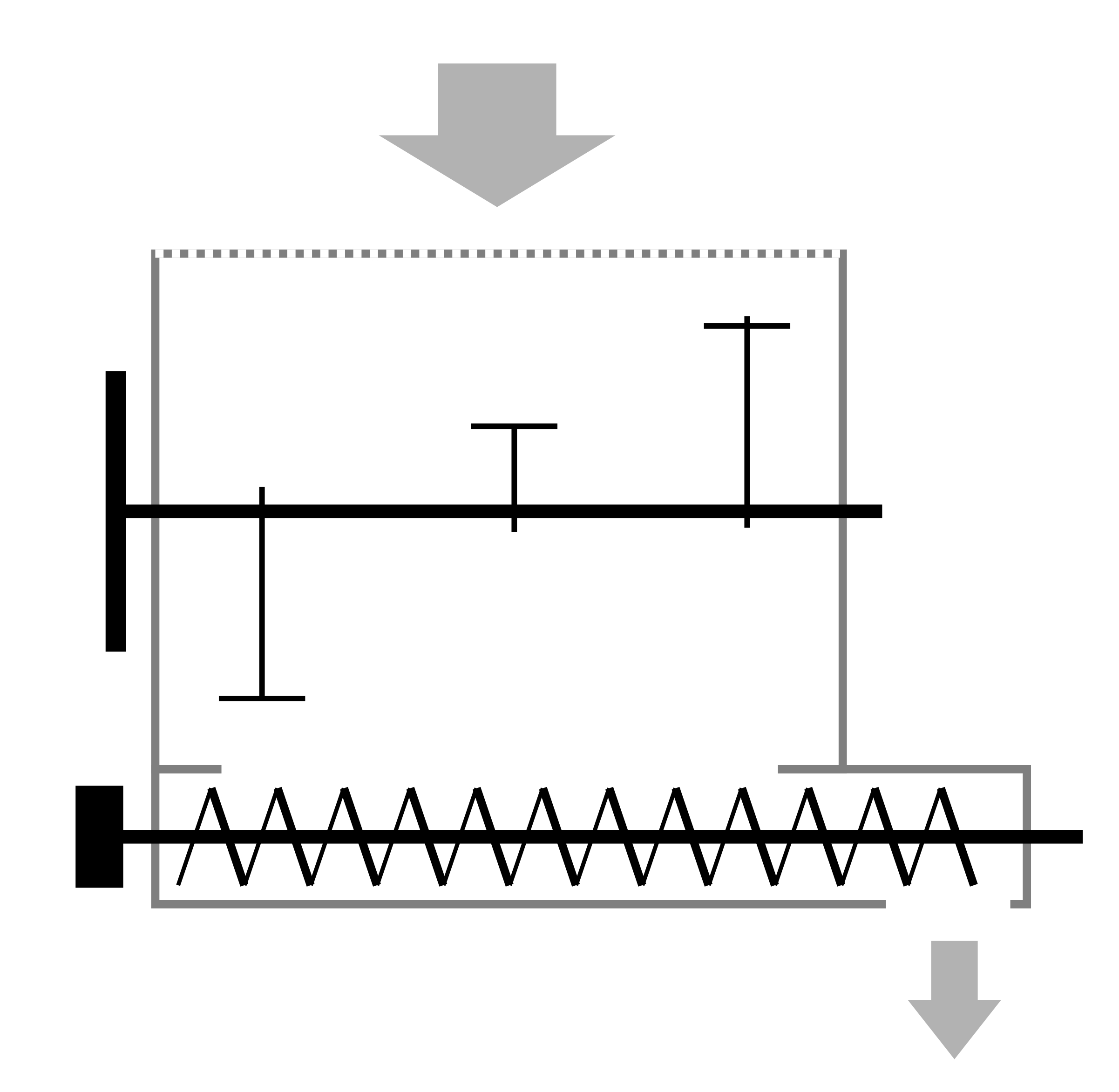 The bottom of the hopper with a horizontal stirrer is open and allows creating a discharge opening practically across the entire length. The stirrer’s rotation speed of 5-6 revolutions per minute is sufficient, ensuring continuous filling of the screw feeder and maximum smoothness of feeding at any discharge speed with the three installed blades. Additionally, the blades rising from the material promote loosening, reducing the load on the drive.
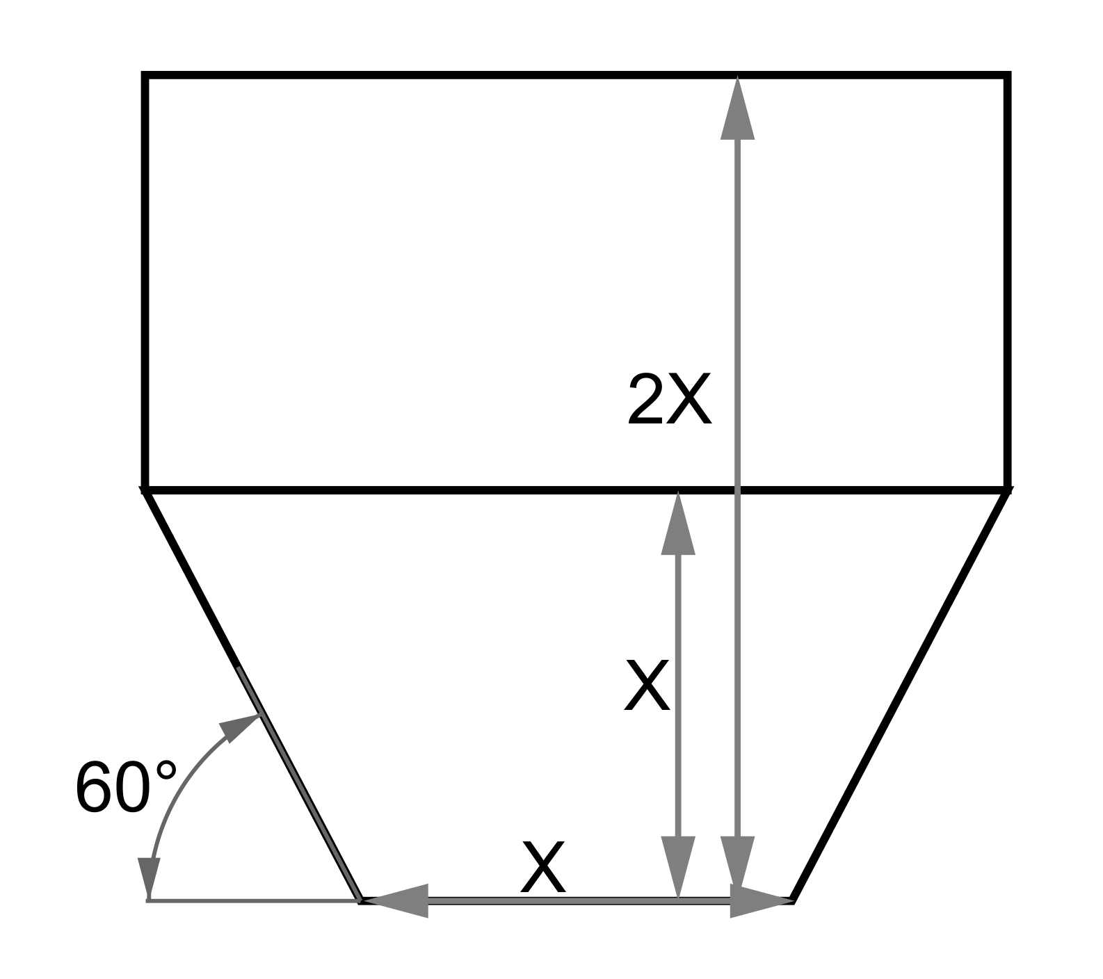 If multiple screw feeders or a fairly wide chain conveyor are located at the bottom of the hopper, it may be possible to manage without a stirrer for dry materials under particular geometric proportions. The height of the inclined walls should be no more than the width of the bottom outlet onto the conveyor or screws, and the total height no more than twice the width of the bottom outlet. The angle of wall inclination to the horizon should be at least 60°. In this configuration, the probability of arching is extremely low. When designing hoppers with a chain conveyor at the base, increasing the working volume is often achieved by extending it 4-5 times relative to its width. In such cases, it is permitted to make the hopper taller, as filling it to the brim is unlikely, and fairly large clumps can form on the ties within, whose periodic collapse creates sufficient vibration for the self-cleaning of the metal body walls.
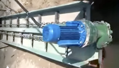
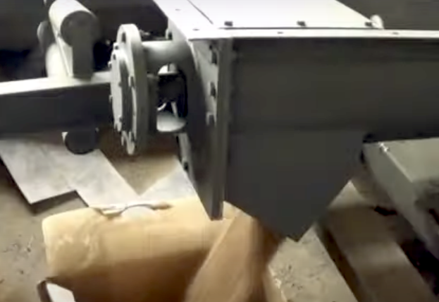
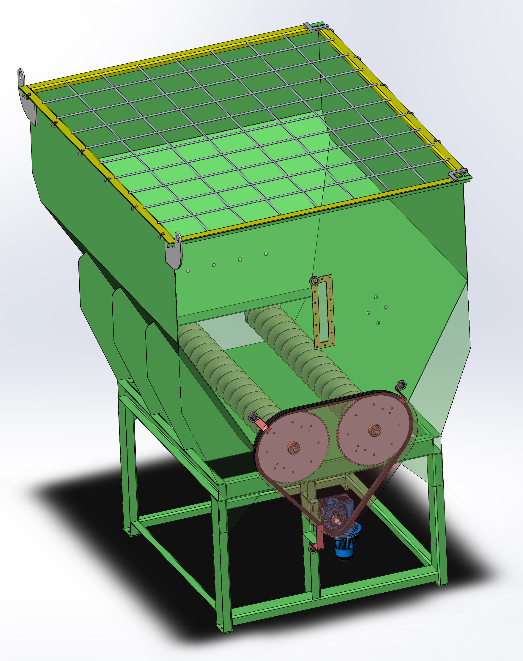 The choice between a screw conveyor or a drag chain is determined by both mechanical and economic feasibility. For a base width up to 700 mm (28 inches) and a length of up to 2 meters (7 feet), it is quite cost-effective and reliable to use two screws with a diameter of 250-300 mm (10-12 inches) or three screws with a diameter of 150-200 mm (6-8 inches), driven by a single motor-gearbox through a chain drive. For larger base widths or lengths, the load on the sprockets becomes too large and uneven, making it much more efficient to use drag chains instead of installing multiple drives and coordinating their operation.
When selecting a drive for a screw dispenser, it is important to consider that the load in terms of torque remains almost unchanged with different rotational speeds, but the motor torque decreases almost proportionally with the reduction of the input frequency. Therefore, to convert a screw conveyor into a dispenser, calculations need to be done twice. First, either calculate or use experience to determine the required torque for the conveyor operation, and from that derive the motor power. Then, considering the possibility of a speed reduction by 2-3 times, increase the motor power by the same factor without changing the gear reducer size. For example, for a screw diameter of 200 mm (8 inches) and a length of 2 meters (7 feet), when used as a conveyor, 0.55 kW (0.74 hp) suffices, which at a 1:60 ratio gives a service factor of 1.44 for the NMRV 075, which is quite reliable. Replacing the motor with a 1.5 kW (2.01 hp) unit reduces the service factor to 0.5, but the gear reducer will never experience maximum load. The presence of a frequency converter setting, which has a torque limit that triggers an emergency stop in case of bearing seizing or large chunks entering, is very helpful. This way you can significantly save on reducers without compromising reliability.
It's also advisable to equip the motor with a forced cooling fan, as the fan's efficiency quadratically depends on speed, and at a threefold speed reduction, its efficiency tends towards zero. Exceptions are made when the frequency converter reduces speed by only 10-20%, meaning its function is merely for fine-tuning rather than wide-range output adjustment.