Drum dryers are undeniably simple in design and calculations, with the ability to adapt to various types of raw materials. They can be made from a variety of readily available materials, ranging from oil barrels to used tanks, which can sometimes reduce their production cost significantly. If we set aside all the drawbacks associated with poorly managed production or attempts to cut costs where it's not feasible, there remain only three significant disadvantages:
Fire Hazard at the Dryer Drum Entry
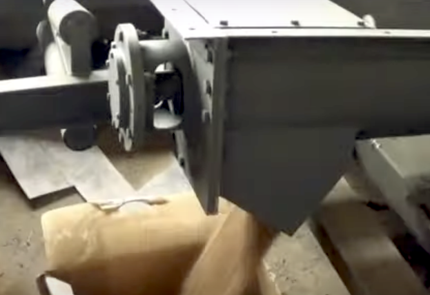
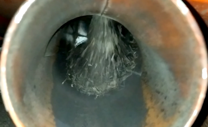
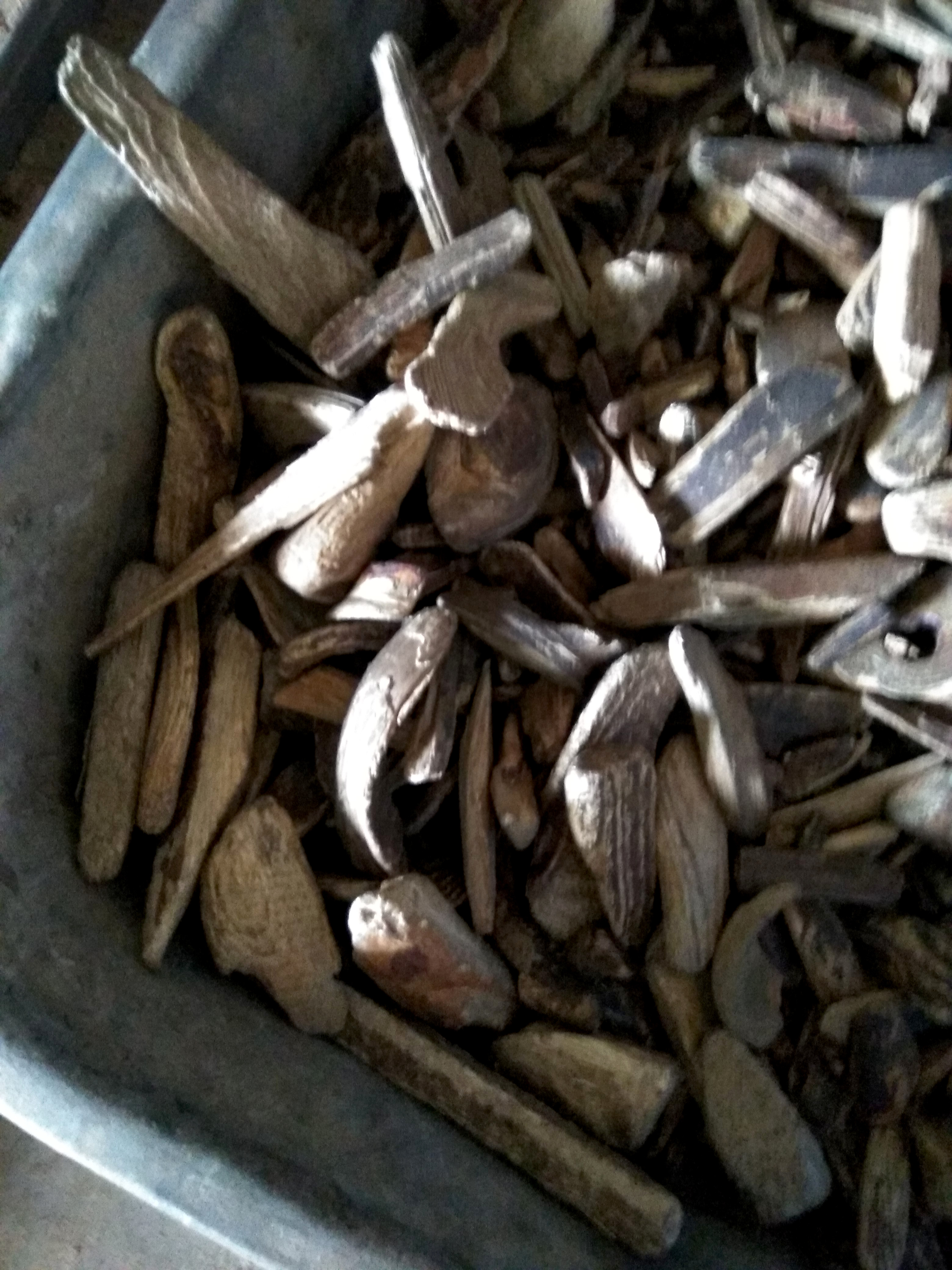 As mentioned earlier, for better capture of the material by the heat agent stream, ladders with plate steps or a steep chute shaped like half of a longitudinally cut pipe are installed. Both options work within a narrow range of flow speeds and feeding rates. The issue is that the material itself, due to its mass, and the chute create a barrier, behind which a gas vacuum area forms. Material falling from the top-mounted devices is sucked into this area near the entry, counter to the flow direction, causing a reverse influx that, due to vortices, directs the chips around the ladder or chute. Most of the material gets picked up again by the stream of the raw material and the agent, returning to the drum. This recirculation results in the accumulation of the largest chips at the beginning of the drum, where they can rub against each other, attaining streamlined shapes. When the temperature of the heat agent rises, the chips overheat and ignite. This does not immediately lead to a fire since there is damp sawdust around, but as the chips burn and become lighter charcoal, they can travel to the end of the drum and reach the already dried sawdust. Here, with active airflow, ignition occurs within 20-30 seconds, first noticeable by the blackening paint on the ducts and cyclone, and then by the parts glowing red-hot from the drum exit to the exhaust pipe leading outside.
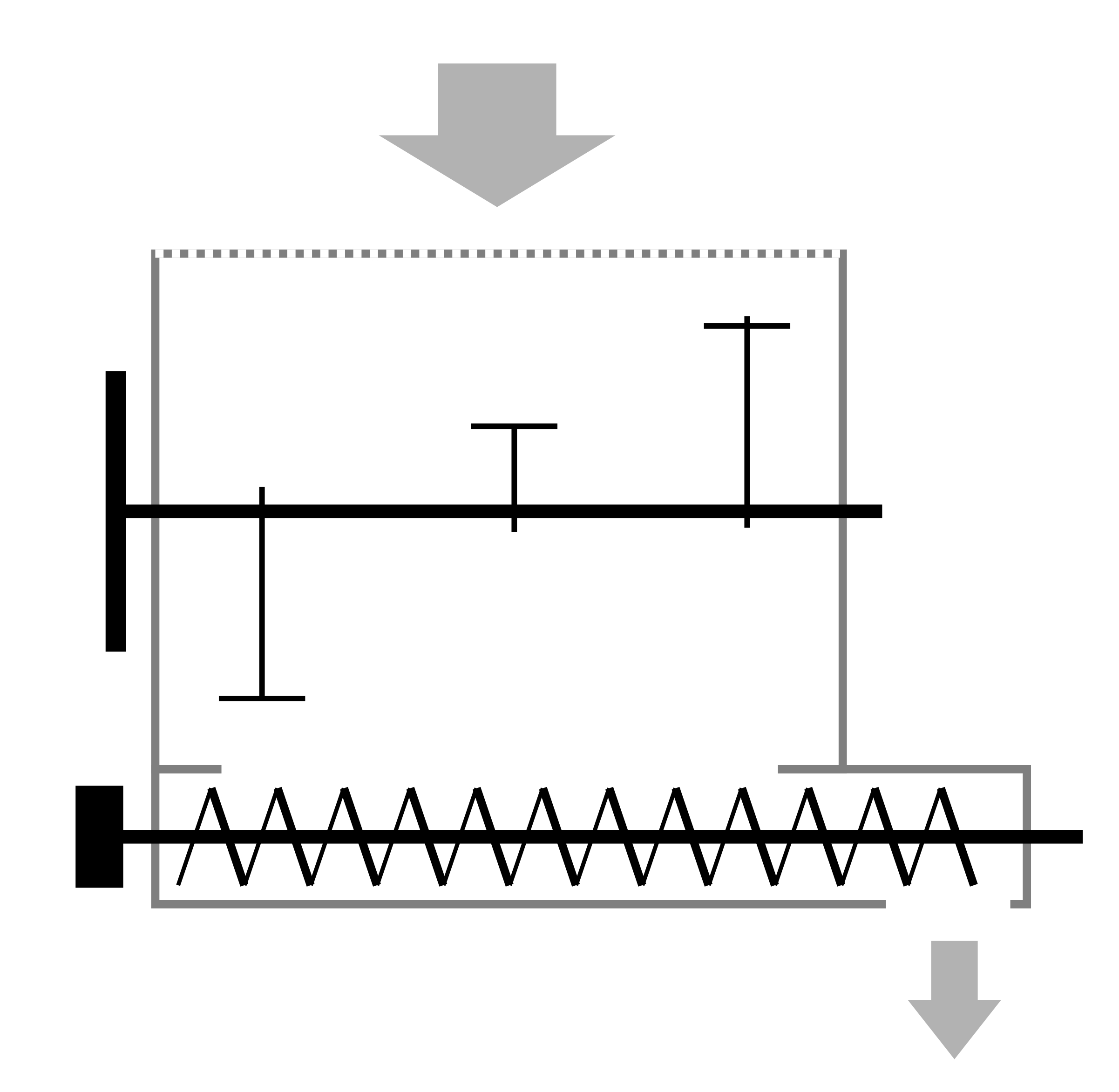
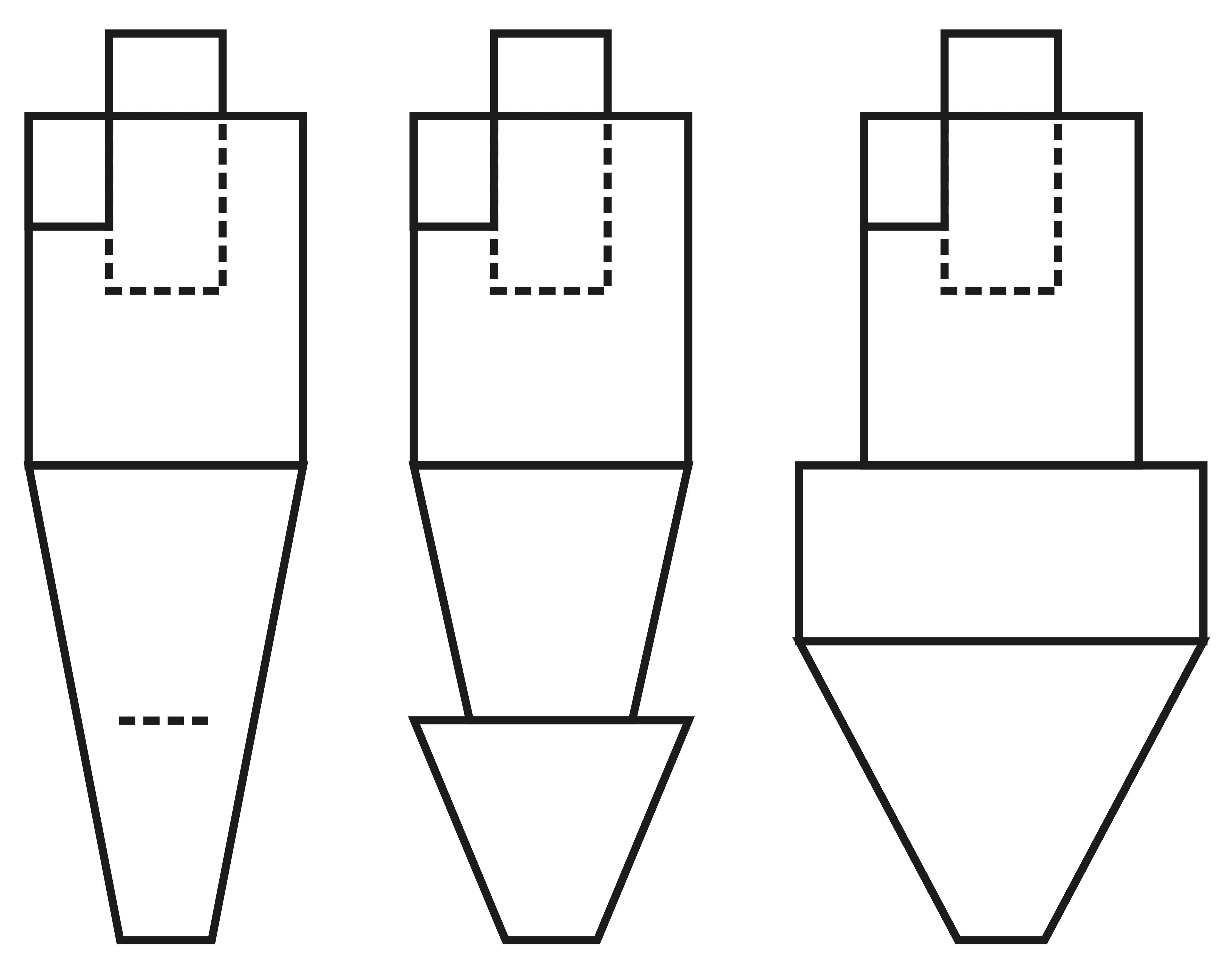
To combat material accumulation in the inlet and at the beginning of the drum, two measures are taken. First, the inlet should be narrowed to increase agent flow speed, achieving no less than 25 m/s (82 ft/s), ensuring that the resultant speed is sufficient to carry off large, wet chips, even in vortices. Second, an immediate baffle should be installed at the drum entry to separate the main volume of the drum from the entrance to prevent reverse material suction by vortices. Inclined screw-like devices should extend at least 0.5 meters (1.6 feet) past the baffle to prevent material piling up and blocking the airflow.
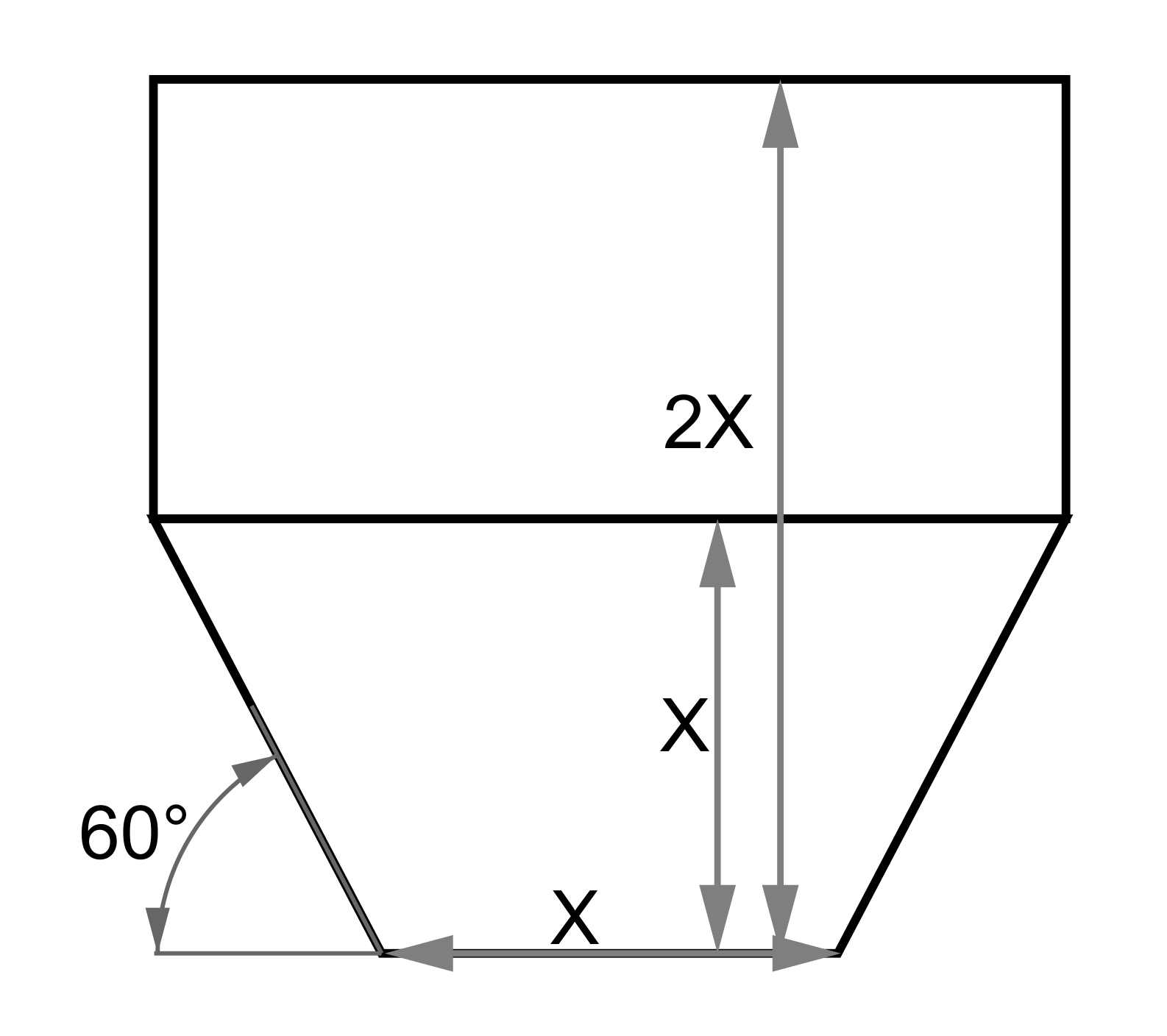
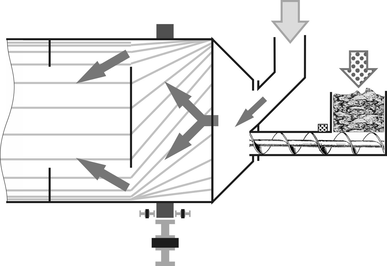 If the drum entrance is already quite wide and the heat agent pipe descends from above, the problem can be solved drastically: position the incoming duct at an angle of no less than 45° to prevent material accumulation, and install a screw feeder in the vertical wall beneath it to feed the material into the drum chamber. With this configuration, the material will have no chance to accumulate in the hot stream, and the screw housing with material can easily be protected from heat with insulation.
Wear of Bands and Support Rollers
Rubber-coated wheels forgive many things, but they usually can't handle drums with a capacity greater than 1 ton per hour. In principle, recalculating the specific bearing area shows that specially manufactured four wheels with a width of 400-500 mm (16-20 inches) can support the load from a drum weighing 12-15 tons (26,455-33,069 pounds). However, the cost of such wide bands and the exclusive rollers themselves becomes unreasonable. Therefore, the simplest way is to install 100-150 mm (4-6 inches) wide steel bands on the drum and slightly wider rollers with a diameter of 300-400 mm (12-16 inches). These pairs resemble railway transport but differ significantly in technological features. The special shape of a railcar's wheel helps it naturally orient strictly perpendicular to the rail, so most of the time, only rolling friction is experienced. For drum supports, no matter how carefully alignment is set, lateral friction is always present. Even a shift of 50 microns per roller revolution translates to a relative dragging of the surfaces by 1 meter per hour (3.3 feet) or over half a kilometer (1640 feet) per month, leading to significant wear. Lubrication is possible if the drive is chain or gear-driven, but it gathers all abrasive dust, and without regular cleaning and replacement, it only worsens the situation.
The second feature compared to railway transport is the interaction between different steel grades on the wheel and rail. Experience installing hardened rails made from strong steel showed a significant acceleration in wear. This happens because hard particles press into the soft rail and cement the surface, similar to vibrating stone drilling with copper tubes. Using a hard rail removes the effect and leads to regular wear. Therefore, fairly soft steel with 0.5...1% manganese content is used, promoting self-hardening of the surface and increasing the alloy's toughness. On the contrary, rollers are made from high-carbon alloy steels or gray cast iron with large carbide crystals. Brittleness is less of an issue than in transport, because rollers do not encounter joints and switches. All of the above indicates that replacing bands and rollers can cost up to half the price of the drying drum, and the service life may reduce to 1-2 years if even one roller is misaligned.
Increased Attention During Operation
Despite the relative simplicity of the drum's structure, the adjoining parts require regular attention and maintenance. Neglect can lead to costly repairs and long downtimes. A worn mobile seal doesn't cause much trouble even with excessive outside air intake until it jams and displaces the drum from its supports, irreversibly deforming the air ducts. When the wear of the bands or support rollers becomes noticeable, it is usually too late to adjust, as the drum begins to "wander" in all directions, risking stoppage or damage during operation. A sudden stop caused by overloading the drum with material inexperience can lead to a serious fire. Before commissioning, it is necessary to test operation at all maximum modes regarding speed, material loading, rotation control automation, and temperatures. It is better to understand the sealing principle, its adjustment, lubrication, and stock up on consumables, even if they will be needed in 1-2 years. It is mandatory to check the presence and readiness of explosion vents, ensuring their area corresponds to the working volume of the dryer. The total minimum area of the vents, expressed in square meters, is calculated by multiplying the volume in cubic meters by a coefficient of 0.05. Explosion vents should also be organized in straight sections of ductwork and cyclones, with the smallest sections having no less than 5 square decimeters (0.5 square feet).
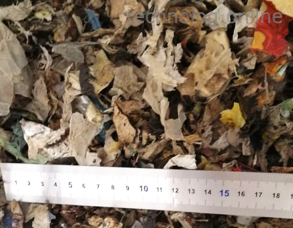
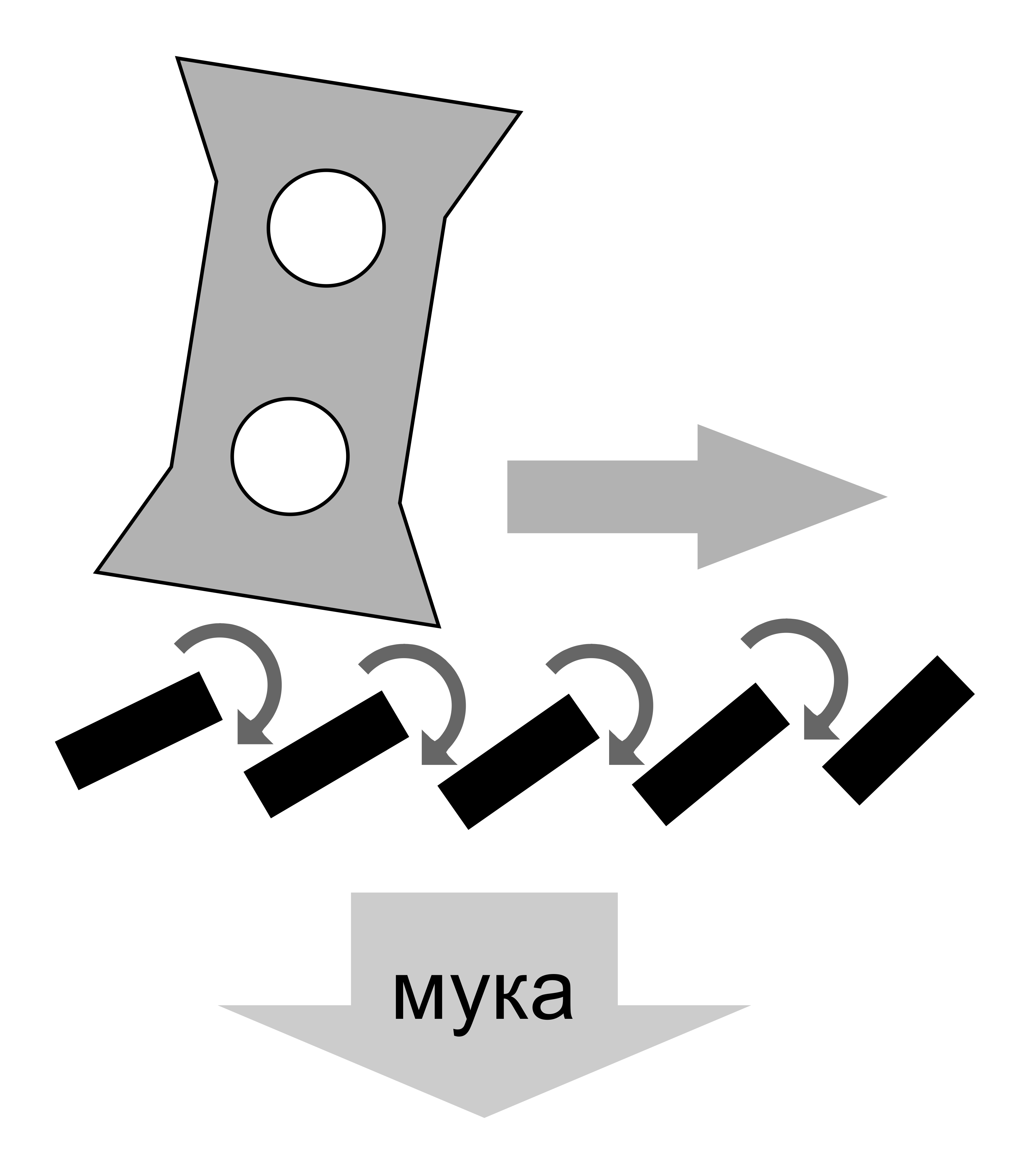
It is also important to understand that the capabilities of the drum are not limitless. While drying sand, sawdust, and wood chips is relatively straightforward, working with sticky raw materials such as manure, distillery waste, or sapropel can lead to balling. Instead of a dry, loose material, the output becomes wet lumps and small pellets, which block air ducts and completely clog the space in hammer mills. For drying clay-like materials, the simplest solution is to recycle 30-50% of the dried material back into the mixer to dilute the initial mass and reduce moisture content. The situation becomes even more challenging with drying RDF (Refuse-derived fuel), which consists of 30-40% polyethylene shreds and similar low-melting polymers. As a result of melting, not only does it form pellets, but it also creates layers on the nozzles, gradually causing the drum to become completely coated with the original material. The presence of low-melting ingredients necessitates lowering the inlet temperature of the agent, and if the construction allows, increasing the amount of heating agent to maintain production efficiency. Generally, this is resolved by installing additional cyclones, replacing the dryer fan, and installing a control damper instead of an explosion vent on the inlet pipe of the drum to supply additional cold air with minimal resistance.