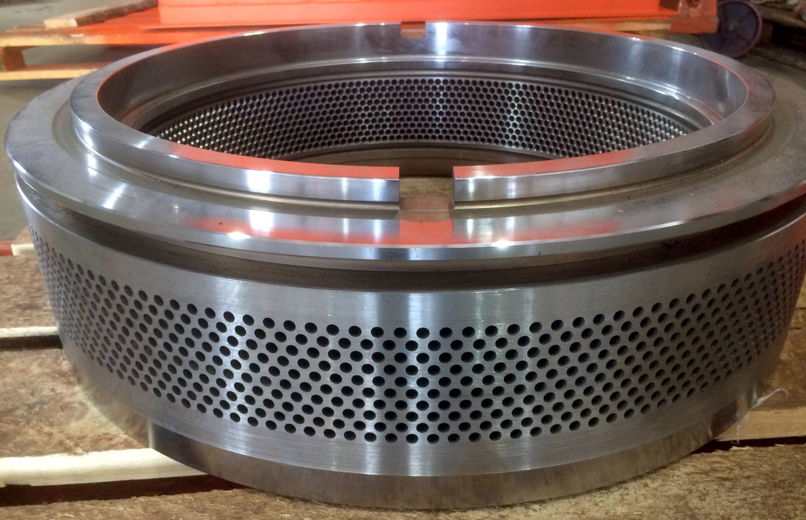
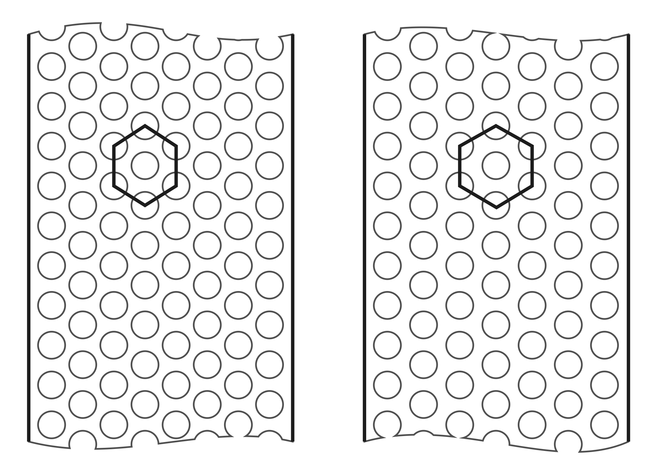
 It's important to mention the placement of holes on the die track. The principle is similar to the perforation ratio on grinder screens: the more holes fit on the track, the higher the productivity and efficiency of the pellet mill, but the strength of the die decreases. The image shows two options for hole distribution on a 480 mm (19 inches) diameter die with a track width of 78 mm (3 inches) and an 8 mm (0.3 inches) die hole diameter. On the left, there are eight rows of holes, and on the right, there are seven rows. In both cases, each row contains 128 holes. From around 2000 to 2020, this was a way to distinguish the origin of dies for the OGM-1.5 pellet mill, as German-made dies had more holes, significantly greater productivity, and easier initial startup compared to Chinese ones. Later, Chinese manufacturers, aware of the consequences of weakening the die, started producing geometrically similar dies as in Germany.
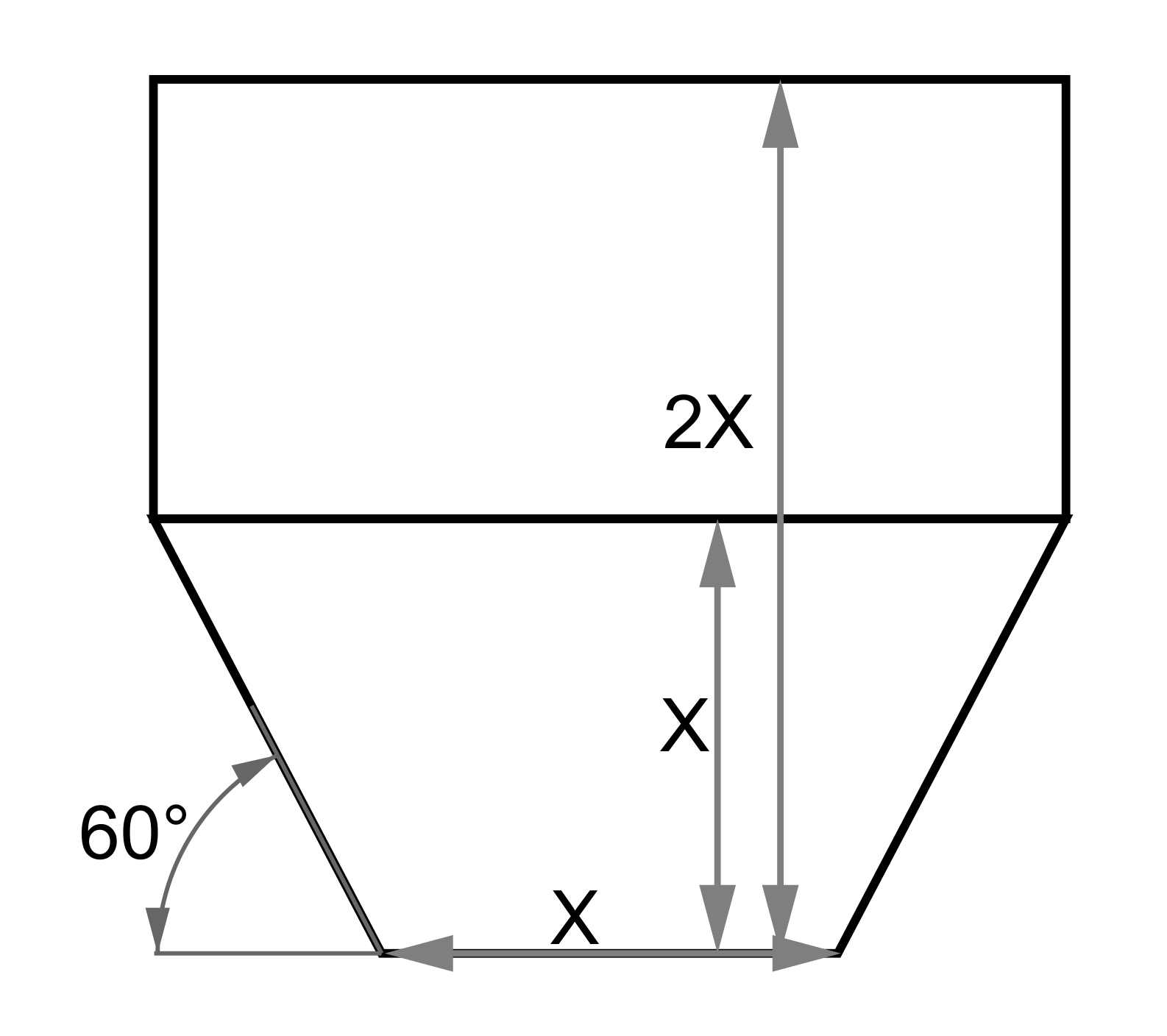
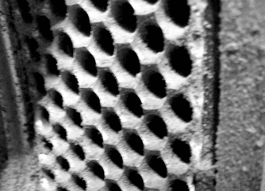
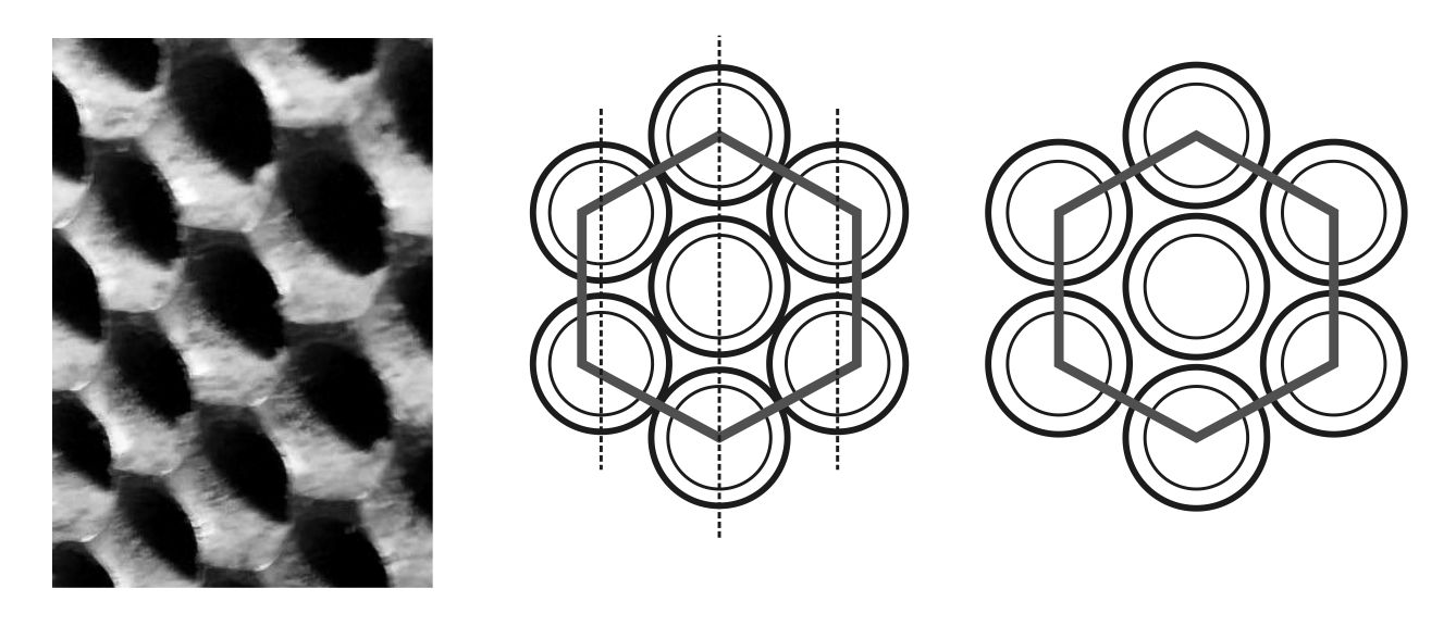 When you look closely at the arrangement of the six nearest holes, it's clear that holes from adjacent rows are closer to each other compared to the holes within the same row. They cannot be placed any closer due to the countersink requirement, which adds approximately 1.3 mm (0.05 inches) in radius. As a result, with denser placement, the countersinks from adjacent rows touch at the edges and later experience significantly more wear from the material, being sharpened like a blade. With this shape, the surface of the die cuts through the heated and compacted sawdust cake with minimal resistance, allowing maximum productivity. Thicker ridges are positioned across the roller's movement, helping to catch the material in the wedge between the shell and the die.
 In German design for an 8 mm (0.3 inches) die hole, the step between holes in a row is 11.75 mm (0.46 inches), and the distance between the centers of adjacent rows is 9.25 mm (0.36 inches), with 2 mm (0.08 inches) left from the edge of the track to the edge of the countersink. For 6 mm (0.24 inches) holes, the same track accommodates 10 rows of holes with 160 holes per row, with a step of 9.42 mm (0.37 inches) in a row and a distance of 7.4 mm (0.29 inches) between row centers. Thus, for the 6 mm option, there's a consistent pattern of a less frequent step in a row than the distance between holes in adjacent rows.
There are basically two types of drilling machines for producing ring dies. The old version involves placing the workpiece on a horizontal rotary table, surrounded by 4 to 8 spindles with drills directed toward the center of the workpiece. The optimal number of simultaneous drillings is six. This setup is convenient for maintenance and provides enough space for fairly powerful drives, allowing for drilling holes up to 16 mm (0.63 inches) in diameter. However, these machines have poor positioning accuracy, making it difficult to produce ring dies with holes smaller than 4 mm (0.16 inches). The new version features a vertically positioned die, and a drilling head that moves from top to bottom with four drills set apart by 20-25 mm (0.79-0.98 inches). This arrangement allows for much more precise positioning of holes and is widely used for the mass production of animal feed dies with holes ranging from 1.5 to 4 mm (0.06-0.16 inches).
Comparing dies with 8 rows of 128 holes made on new machines to dies with 7 rows of 126 holes made on old machines, there is a 42% reduction in processing time. This is because the old machine can drill 6 holes simultaneously instead of 4, and has one fewer row. Therefore, by placing orders with facilities that specialize in fuel dies with larger hole diameters and operate older machines, you can save up to 20%, assuming that the die's performance and lifespan satisfy the technologists.
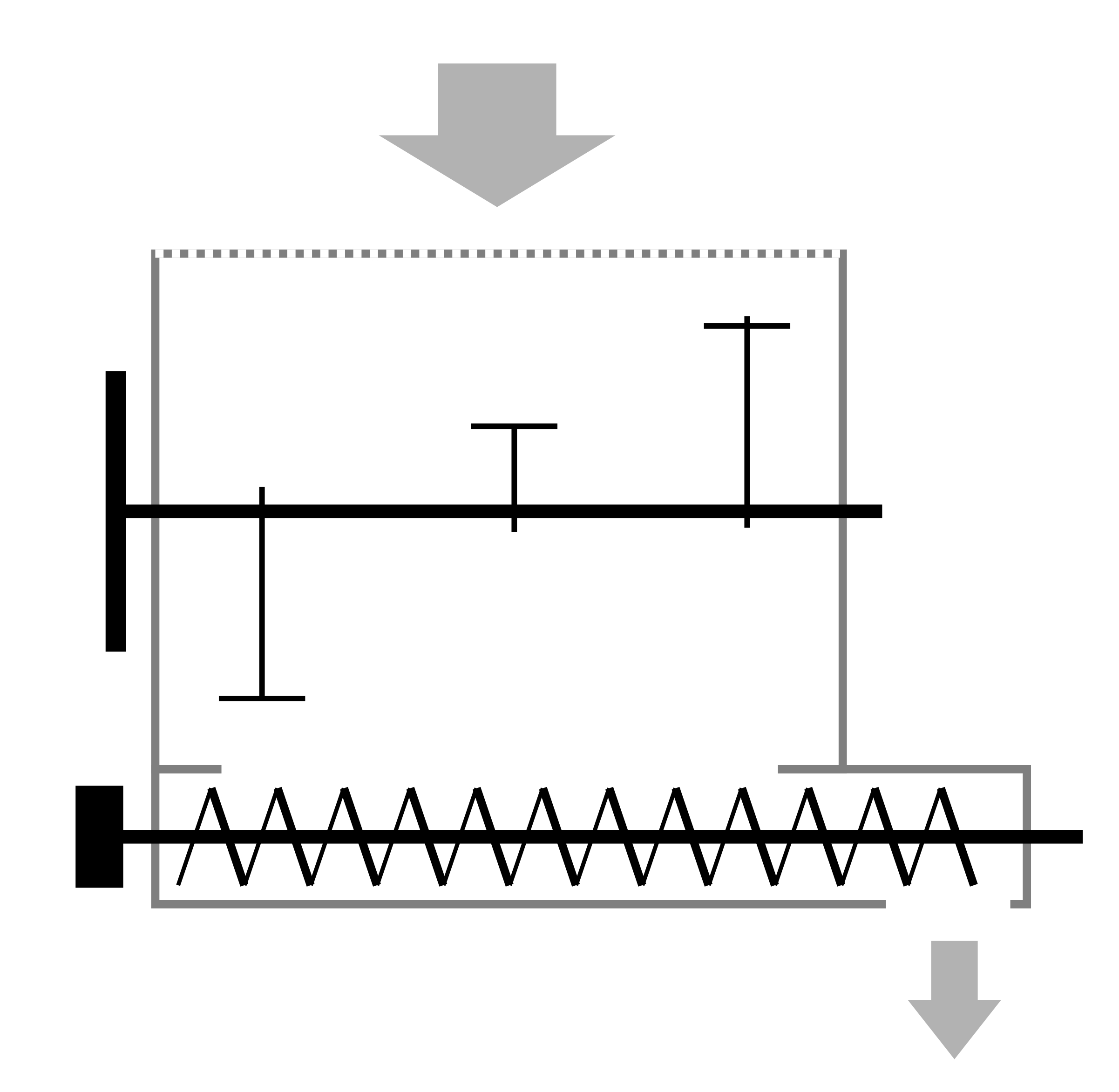
There is another important detail for almost any ring die: its track should be higher than the adjacent body by a height designated for wear. If the track and the rest of the part are on the same surface, raw material will press next to the track and push the rollers away from the die. Additionally, less wear on the edges compared to the middle of the track will not allow the installation of new rollers without leveling the die. If the design does not allow for a protruding die track, grooves of 8x8 mm or 10x10 mm are made next to it. These grooves allow the edge of the shell track to pass above, leaving a gap for the free exit of excess material without being trapped in the closed part.
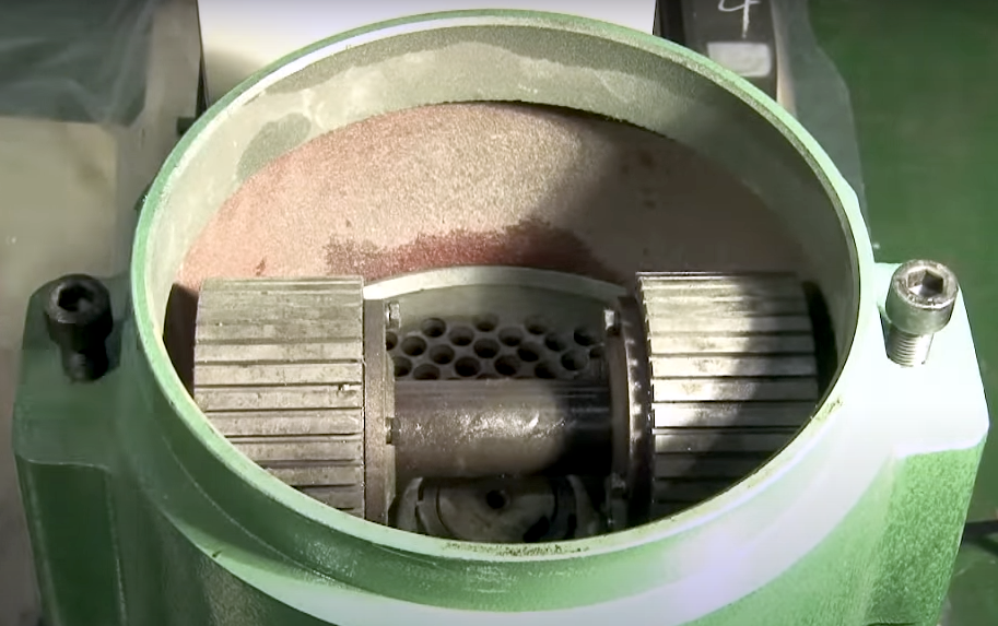
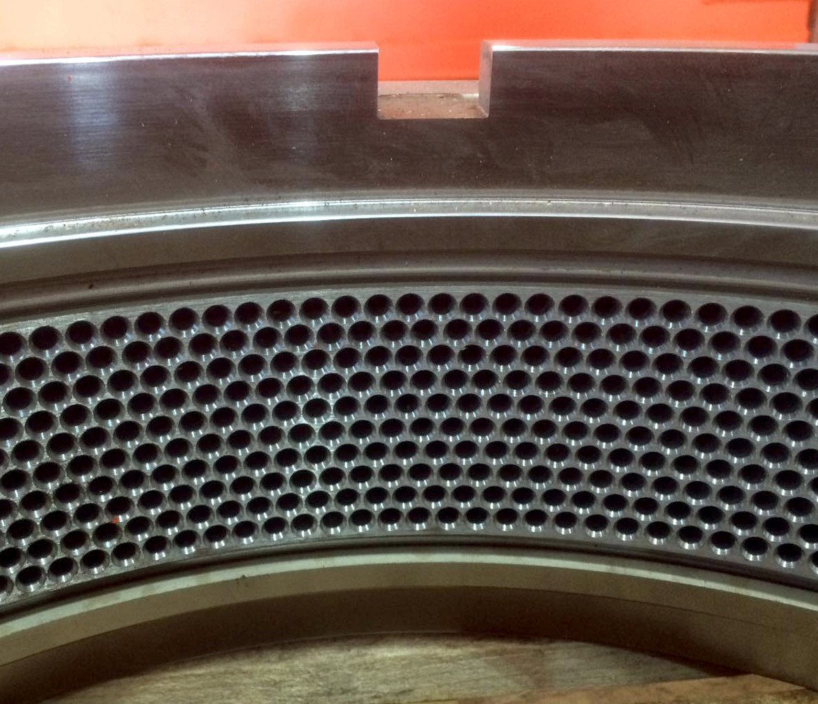
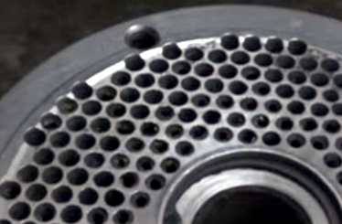 With a flat die, things get much more interesting. Hexagonal placement of the holes leads to dead spots where the shell hits the raw material and bounces like hitting bumps. This results in impact load, increased clearance, and unstable operation. The photo shows a rolled strip from the roller, within which is part of the track without holes. In such an arrangement, more holes should ideally be made, even though the ones at the edges will not fully function. Hexagonal hole distribution still works quite well for dies with a diameter of 600-1000 mm (24-39 inches), as even distribution of the holes over the area provides the most gentle and efficient pelleting, but for diameters up to 300 mm (12 inches), the situation looks like the photo. In addition, it is impossible to cheaply create a protruding track or its limiting groove on small dies with such a pattern, as this would require milling along a complex trajectory. This is a note for mass die manufacturers using CNC machines where drilling and milling will be embedded in a single program.
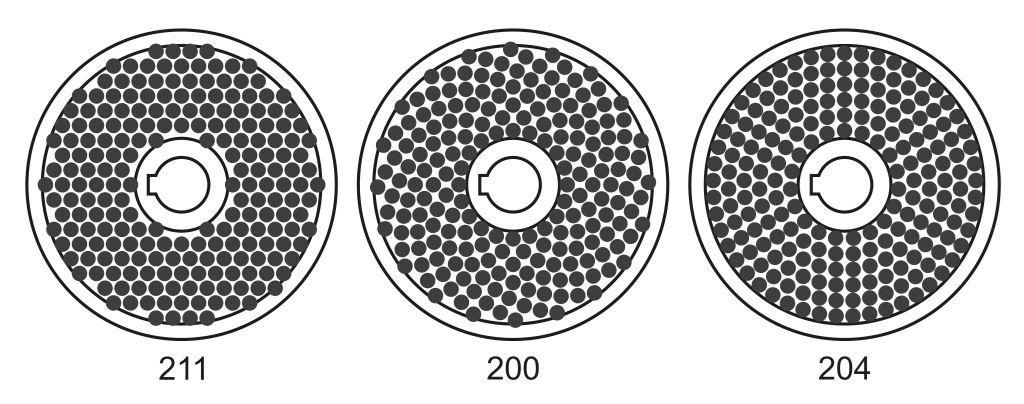 The second option is the concentric arrangement of rows of holes, with the spacing between rows decreasing as the diameter increases, and the holes of the rows interleave each other. The illustration compares the arrangement of 8 mm (0.3 inch) holes with countersinks to 10 mm (0.4 inch) for a die with a diameter of 200 mm (8 inches) and a track width of 60 mm (2.4 inches), with circles showing the countersink size. In the hexagonal layout, the spacing between holes is 11 mm (0.4 inch), taken as an average of a more or less sturdy execution from ring dies experience. In the concentric arrangement, the diameter of each row was chosen so that the centers of the holes in adjacent rows maintained that 11 mm (0.4 inch) gap. Surprisingly, almost the same number of holes fit. The second option removed dead spots near the center but left many along the edges, so the geometry complication did not yield the expected effect. In the third option, row diameters increase with a consistent step of 10 mm (0.4 inch), which is noticeably more than in the German execution of the ring die and helps maintain good strength. The step within the row is about 11.6 mm (0.5 inches) with minor deviations. As a result, almost the same number of holes fit as in the first two options, but without blind spots at the edges of the track and with the possibility of turning a groove on both sides of the track. As shown in the illustration, quite a few holes touch the edges of the countersinks, and increasing them would lead to some crossover in neighboring holes, which hardly affects the die behavior. Moreover, there have been multiple cases where a piece thicker than 15 mm (0.6 inch) broke off the track after large bolts fell into the raw material, and the dies continued to function normally for their usual lifespan. Concentric arangement of hole rows with consistent spacing both in the row and between rows provides much more stable and long-lasting work with proper surface treatment and hardening, and the perforation percentage is practically no different from other types of hole distribution.
In litter-free manure, a known issue is the presence of feathers. These fibers lie on the track, accumulate, and clog the die. The reluctance to install a hammer mill and the high moisture content of the raw material, which results in pellets with a matte surface, led to experiments using unusual dies. Their holes are positioned 1-1.5 mm (0.04-0.06 inches) closer to each other with minimal countersinking. The counter bore is only 0.5 mm (0.02 inches) larger than the hole diameter. During operation, sharp edges are formed at the entrance of the holes, which help cut the fibers and produce pellets with 12-14% moisture content and high productivity.