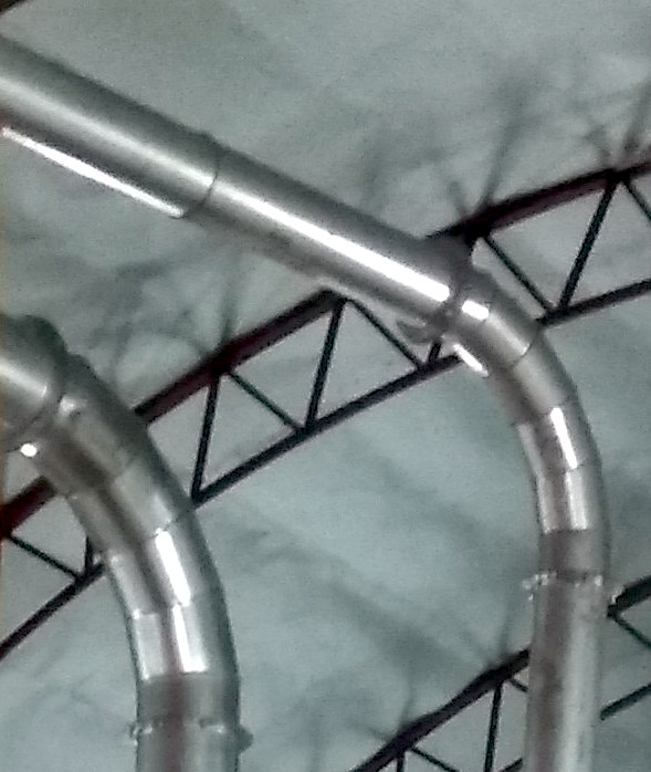
 Transporting raw materials with an air stream is the cheapest in terms of equipment purchase and the most expensive in terms of energy consumption. Compared to regular ducting, pneumatic transport requires much more attention to the strength and wear resistance of the pipe. For small diameters, a spiral pipe made of galvanized metal is suitable, as well as plastic sewer pipes. It should be noted that using plastic ducts requires wrapping them with grounding wire to prevent hazardous electrostatic voltage buildup. Another distinguishing feature from regular ventilation is the increased turn radius, which equals two pipe diameters. This significantly raises the cost of bends but greatly reduces resistance to material and air flow. The most successful pneumatic transport solutions happen when active blowing or material transfer already demands a high air flow rate, naturally extending the process. In pellet production, there are three such areas: heat agent drying, dry material grinding, and pellet cooling.
During drying, 5-10 cubic meters (176-353 cubic feet) of air are used for each kilogram (2.2 pounds) of raw material, meaning the dust concentration is 100-200 grams per cubic meter (0.1-0.2 lb/ft³), and considering the high vapor content, precipitation occurs quite effectively in most types of cyclones. For fine wood material with a fraction ranging from sawdust to small chips of 10-15mm (0.4-0.6 inches), the optimal flow speed is considered 15-20 m/s (49-66 ft/s), where there is a high probability of avoiding material settling and the energy costs are not critical. The optimal speed for pneumatic transport is usually 150-200% of the velocity at which particles begin to hover or free-fall. This figure is heavily dependent on bulk density, so for pellets and their crumbs, it is advisable to double the flow speed compared to sawdust conveyance. The minimum speed at which clusters begin to accumulate in horizontal sections and turns is 10-12 m/s (33-39 ft/s). Based on this, the duct diameter calculation is done at 20 m/s (66 ft/s), with the possibility of reducing the flow by 20-25%, for example, to increase drying temperature.
| Evaporated Water Quantity, kg/h | dT=250°C, m³/h | dT=320°C, m³/h | Cross-Section at V=20 m/s, m² | Calculated Pipe Diameter, mm | Cross-Section at V=15 m/s, m² | Calculated Pipe Diameter, mm |
|---|---|---|---|---|---|---|
| 700 | 6720 | 5250 | 0.0933 | 345 | 0.0972 | 352 |
| 1000 | 9600 | 7500 | 0.1333 | 412 | 0.1389 | 421 |
| 1500 | 14400 | 11250 | 0.2000 | 505 | 0.2083 | 515 |
| 2000 | 19200 | 15000 | 0.2667 | 583 | 0.2778 | 595 |
| 2500 | 24000 | 18750 | 0.3333 | 652 | 0.3472 | 665 |
| 3000 | 28800 | 22500 | 0.4000 | 714 | 0.4167 | 729 |
| 4000 | 38400 | 30000 | 0.5333 | 824 | 0.5556 | 841 |
For calculating pressure loss in ducts, it's acceptable to use simple online calculators in which you input air flow, pipe diameter, its length, and number of elbows. For example, for 3600 m³/h (2120 cfm) with a diameter of 250 mm (10 inches) and four 90° bends, the flow speed is 18 m/s (59 ft/s) and pressure losses are 1.1 kPa. However, using a duct with a diameter of 200 mm (8 inches), you get a speed of 29 m/s (95 ft/s) and losses of 3 kPa, which is the limit for most dust fans. In advance, it turns out that the diameter and configuration of the duct determine the real air flow. The range of fan performance is quite large; the minimum and maximum values can differ by 2-3 times. But in the duct, at the speed limit of 20-25 m/s (66-82 ft/s), there is a sharp increase in resistance, which ultimately determines the established flow speed and performance.
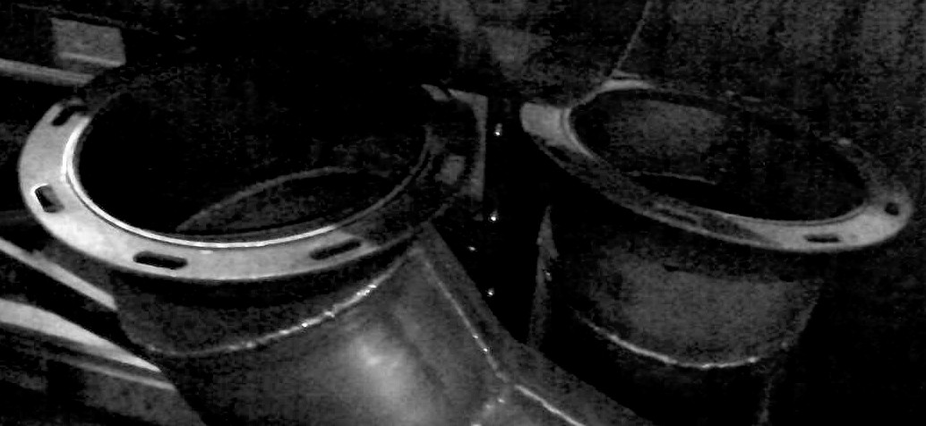 The diameter of ducts is chosen from a range of standard sizes in the region, which are mass-produced by ventilation companies. It should be noted that dryers usually operate under vacuum, so when choosing the wall thickness of the ducts, the maximum possible vacuum for the fan should be checked, taking a 1.5-2 times safety margin. This precaution is necessary in case of sudden blocking of the dryer opening by a damper or too sharp a closure of the heat generator's firing pipe. Experience shows that for most dryers, a duct wall thickness of 0.7 mm (0.03 inches) is applicable for diameters up to 300 mm (12 inches), a thickness of 1.5 mm (0.06 inches) for diameters up to 500 mm (20 inches), and a thickness of 3 mm (0.12 inches) for diameters of 700-800 mm (28-32 inches). The most convenient for manufacturing and installation are duct sections 2 meters (7 feet) long with flanges at the ends. The length of straight sections is chosen based on the available width or length of steel sheets. Flanges also serve as stiffeners, and the slots in them allow orienting bend connections in any direction. During assembly, high-temperature silicone is typically used, applied with a caulking gun. Although its durability is usually rated up to 350°C (660°F), reaching slightly higher temperatures without strong vibrations and with sufficiently large flanges doesn’t lead to joint leaks. Paste-like compositions with thermal resistance up to 800-1200°C (1500-2200°F) mostly consist of clay-like binders, so even with slight vibration, they quickly chip out of gaps.
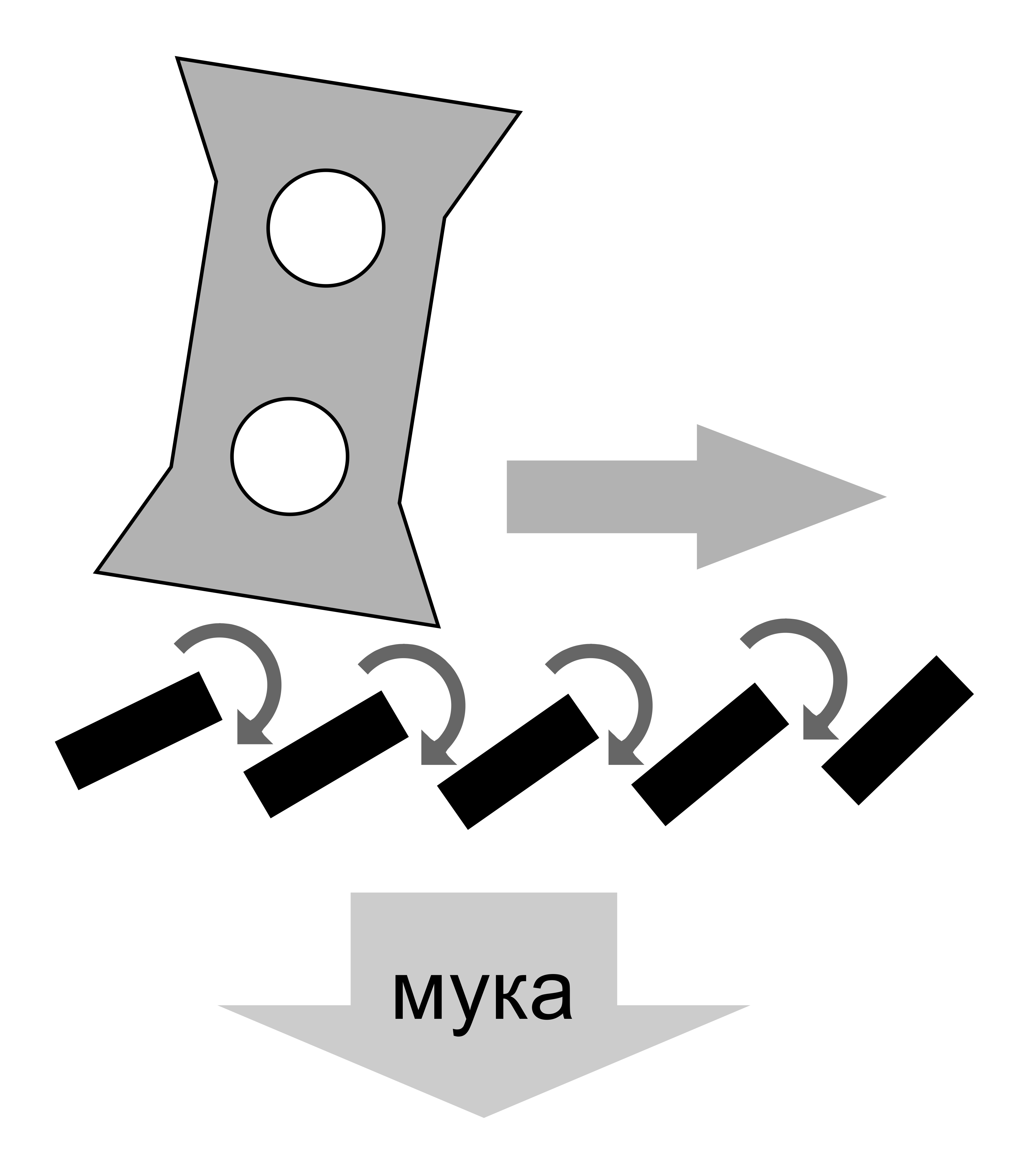
When transporting dry fine material from the hammer mill, also known as flour, 1-2 cubic meters (35-70 cubic feet) of air are used per kilogram (2.2 pounds), meaning dust concentration can reach up to 1 kilogram per cubic meter (62 pounds per cubic foot). Settling the mixture of fine particles and dust is very challenging. Several stages of settling and cleaning are applied, as explained in more detail in the section on air aspiration. The main distinction in pneumatic transport of hammer mills is that noticeably higher pressure or vacuum and 2-3 times higher transport speed are used. This is a carryover from food mills, intended to maintain high productivity when processing grain, which has three times the bulk density of wood waste. Although it results in additional electricity costs, this setup has an important advantage: short-term increases in raw material feed or feeding wet wood do not lead to emergency shutdowns. Pipes do not clog, and, within allowable load currents, operators have sufficient time to respond. When dry materials are subsequently fed, the ductwork self-cleans and operates normally.
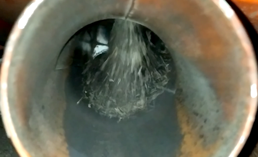
Noticing this property of screen hammer mills, they are widely used for processing raw wood and bark by increasing the air flow another 2-3 times. This not only raises electricity consumption but also delays the need for a complete cleaning of the pneumatic system. With moisture levels up to 30-40%, such a system can work relatively stable. However, with the natural moisture content of green logs and especially in severe frosts, moisture droplets expelled during crushing reliably coat the internal surfaces of the pipes, almost completely obstructing the passageway.
Of course, these phenomena largely depend on the quality and fractional composition. If the wet chips are large enough and do not contain sawdust or small resinous pieces of bark, pneumatic transport may be justified when less energy-intensive transport methods are not feasible. Large pieces help clean the surfaces but also accelerate wear, particularly at duct turns. Due to higher density, the flow speed must be at least 23-25 meters per second (75-82 feet per second) for pneumatic transport of raw chips.
Challenges with dust transport in humid air also affect cooling columns. The majority of the air passes through the pellets, carrying away fine particles, as well as heat and moisture. In this section, a fan with a vacuum of 1.2-1.5 kPa (0.175-0.218 psi) is usually sufficient to overcome the resistance of the pellets, two outlets, and a cyclone. Ten percent of the air is used for pneumatic transport of fairly large and heavy screenings, where an increase in flow speed to 15-18 meters per second (49-59 feet per second) and a vacuum of more than 2.5 kPa (0.363 psi) are required. Separating systems complicates and increases the cost of the equipment, so the optimal approach is using a fan with sufficient vacuum for pneumatic transport and a regulating damper. Partial closure of the damper optimizes speeds and vacuum in both paths. Like any other engineering solution, the combination of two flows is criticized for allowing a large amount of screenings to pass along with warm moist air, which under certain conditions can lead to regular and total material buildup in the pipes. On the other hand, with proper calculation, design, and adjustment, pellet fragments effectively scrub fine moist dust from surfaces.
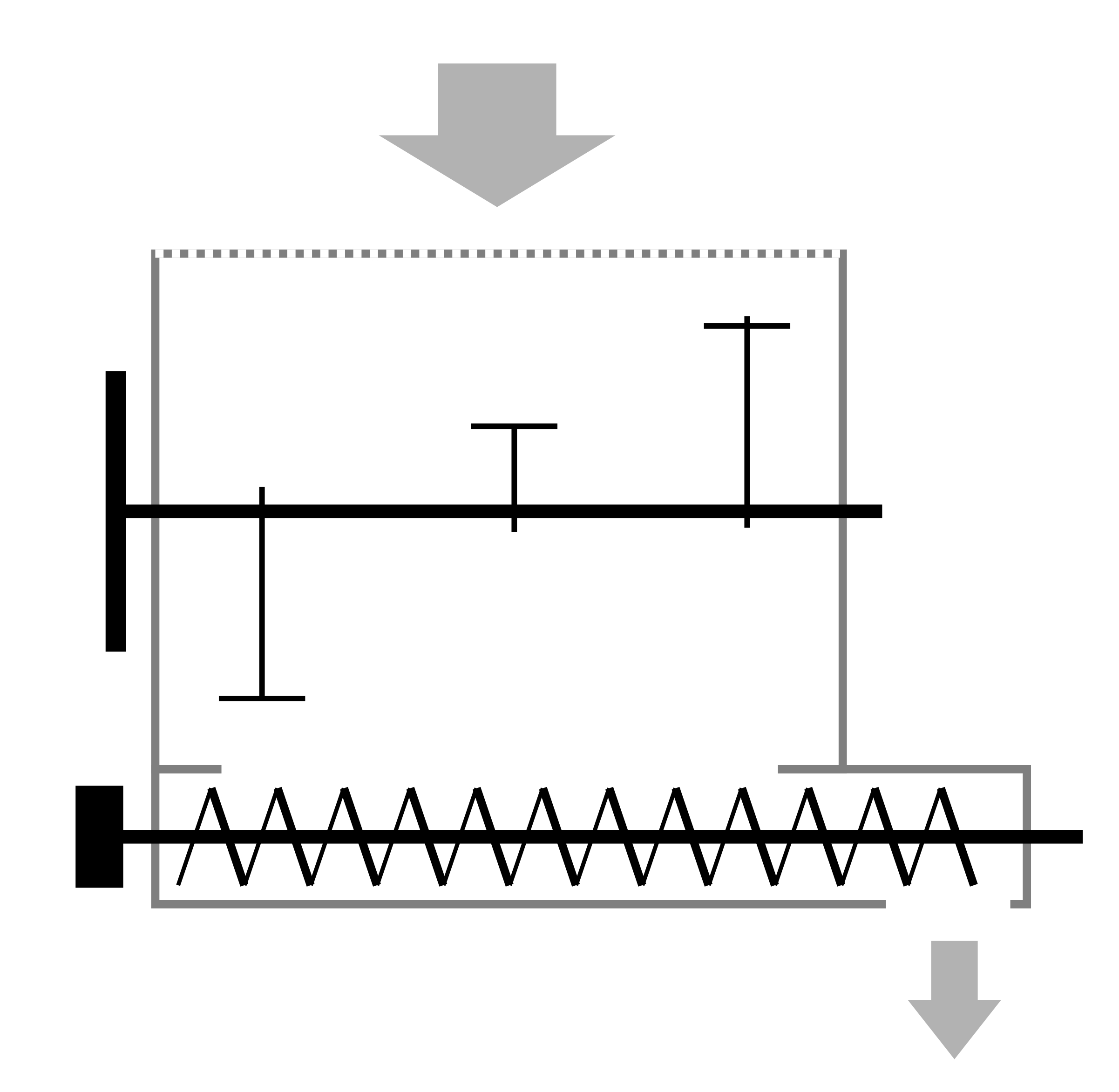
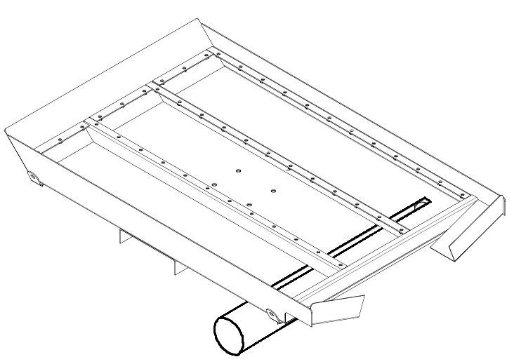 Common complaints about weak airflow under the cooler sifter typically occur when the ejector design allows it to become completely clogged with fines, which can be present in the pellets much more than the usual 5-10% during process setup periods. This is exacerbated by the intermittent operation of the vibrating screen when the accumulated product on the screen suddenly releases fines and dust. To prevent such situations, it is necessary to ensure at least a 50% clearance for air passage with any feed of fines and, if possible, limit peak feeding. The simplest way is to position the ejector pipe across the sifter with an open air inlet on one side and an outlet towards the fan on the other side. In the top of the pipe and at the bottom of the vibrating screen, a slot is cut along almost the entire length of contact, through which fines and some air enter the ejector. The width of the slot should be at least twice the diameter of the screen mesh to prevent material from becoming stuck. The maximum width should be calculated so that the clearance area of this slot is approximately equal to the duct's cross-section.
 This design promotes self-regulation of the device. When there are few fines, the airstreams through the slot and the suction pipe are roughly equal. As soon as the clearance starts to noticeably block with fines, most of the air goes through the round entry into the pipe. In this case, the linear velocity of the flow increases at the beginning of the pipe, and the first captured particles accelerate, helping to remove the main mass of fines from the ejector. The horizontal orientation of the slot and its small width ensure very even material intake, allowing operations to remain stable at minimal required vacuum and flow speed.
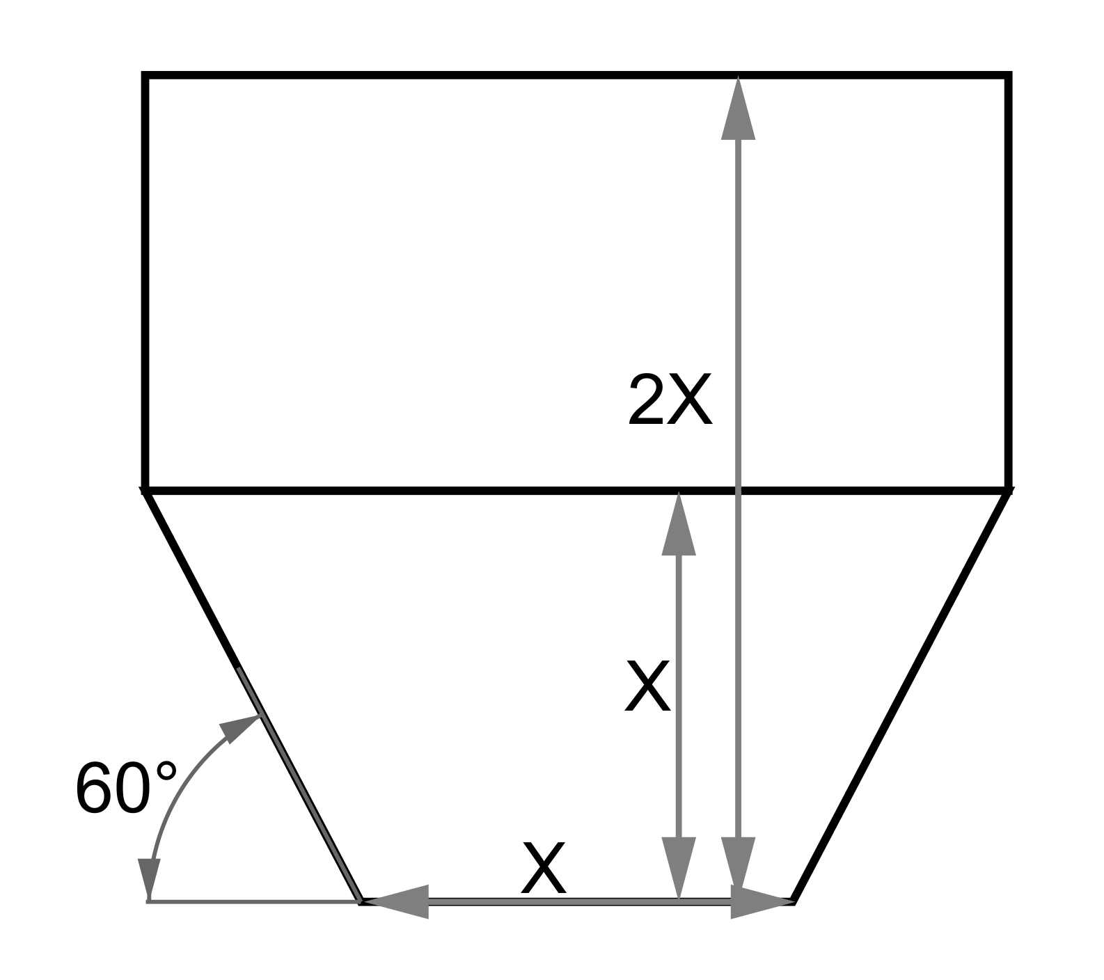
The illustrations show another subtle advantage of the device – its compactness is invaluable under tight size constraints for mobile equipment applications, as well as integration into existing production lines. It should be noted that when using pneumatic transport after air-lock devices such as the rotary airlock, screw conveyor, and other air-sealing equipment, where a funnel must be used, it is also necessary to provide a slot along the duct with a cross-sectional area equal to the duct's cross-section. Additionally, openings or louvers should be provided in the funnel walls to allow air intake, which will draw material into the duct slot. Otherwise, eddies and backflow will be created in the funnel, accumulating clumps and gradually completely clogging the transition. If the fraction is large, it will be necessary to increase the duct diameter and, consequently, the airflow. When collecting from several such points, the ejectors should work in parallel, merging into a larger diameter duct. Sequentially connecting pickup points while ensuring 30-50% air suction from outside can lead to gigantism and excess energy consumption for pneumatic transport.
Sometimes raw materials are fed by a screw or through a lock with a flange smaller than the duct diameter. This method leaves no room for material accumulation, but from the point of raw material feeding from the screw to the first turn and between the raw material feed and the fan, so-called "acceleration sections" are usually left, 5-8 times the duct diameter in length. In these sections, flow speeds equalize, and the material is relatively evenly distributed in volume without subsequent settling behind the turn. This method is used when feeding raw materials into a dryer or for transporting raw materials over long distances in pressure-operated systems. In large diameters and with heavy, wet material, angled grates like ladders are installed in the ducts to prevent rapid falling clumps from settling on the lower duct wall, leading to subsequent settling and narrowing of the clearance.
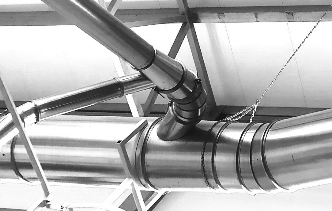 In establishing a centralized aspiration system for the entire production line, conical transitions are used, from which smaller diameter branches diverge at an angle of no more than 45°. This design reduces hydraulic losses in air flow by minimizing turbulence. Such a system makes it much easier to adjust flows using dampers. Pipes made of stainless steel, including the conical transition, are used at points where steam is generated. Afterward, the steam mixes with a larger proportion of air and dust, making galvanized pipes sufficient.