Inadequate Automation Behavior
It is quite common for the control panel to be connected by poorly trained specialists. The appropriate cable usually has four wires: three phases and one neutral. By mistake, the neutral wire is connected to the grounding of the panel instead. And the neutral of the control panel remains unconnected. Further, when trying to turn on the system, errors begin to pop up, which can sometimes be resolved by adding extra wires. Ultimately, at some stage of startup, a long short-circuit occurs through temperature sensors or other instruments to the ground, resulting in half of the control system burning out. Properly, the neutral wire should be connected to the neutral of the control panel, and grounding should be connected to the common grounding of the shop. This is available for each piece of equipment and consists of a common device with rods driven into the ground according to standards. Connecting the cable neutral simultaneously to the neutral and the chassis of the panel is not allowed, even though it enables starting the equipment. Such improper connecting will at a minimum result in significant fines during safety inspections. At maximum, it might lead to injuries due to failed grounding in case of insulation damage on any machinery. Although standards for electrical equipment differ between countries, the principle of separating grounding safety from the neutral for operating three-phase equipment should be clear.
Frequent Failure of Initial Equipment in Pelletizing Line
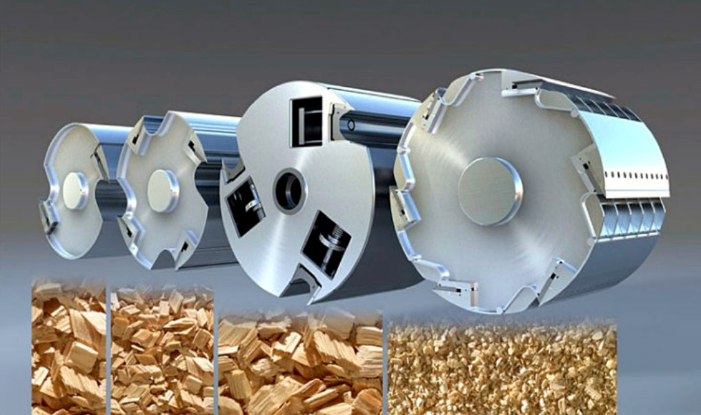
Blades of the chippers and shredders are sharpened as the load increases and performance decreases. Deep indentations and chips appear due to the presence of metal parts and gravel in logs and timber slabs. Stones usually accumulate during storage on deteriorating surfaces of concrete sites if they are not cleared timely. They embed into the surface under the weight of the wood so deeply that even debarking cannot remove them. Regular clearing and storage on special stands can significantly ease processing work.
Metal inclusions deep within the trunk are often found when logging is carried out in areas that were once battlefields. Fragments, bullets, and even unexploded ordnance can be at the heart of a surviving tree trunk. Preventing such occurrences is difficult. However, setting up for producing larger chips reduces the likelihood of the blade encountering a fragment. This increases the load when further crushing raw chips in the hammer mill, but overall extends the maintenance interval. If there are many inclusions, an automatic magnetic separator should be considered instead of a static magnetic plate.
Extreme Increase in Sawdust Moisture Before Drying
When frozen dirt is present on slabs or logs, the average moisture content of the resulting chips can reach 75-80%. Consequently, twice as much moisture must be evaporated for every ton of final product. Considering this same chip is used as fuel and its caloric value is halved, the total wood consumption may reach 6-7 tons per ton of pellets. This assumes that the heat generator can maintain its output with low-quality raw material. Factoring in productivity loss, it is more cost-effective to invest in shelters for rain protection or at least equip open storage areas with proper drainage channels and pipes.
An amusing incident happened at one of the facilities where fresh and relatively clean sawdust was being processed. Come spring, the productivity of the dryer suddenly decreased several times over. It became necessary to periodically stop the pellet mill because it was difficult to adjust due to a lack of raw materials. It turned out that one of the conveyors feeding the raw materials was recessed into a sump where water was flowing as snow melted on the roof and the area near the shop floor. Essentially, the chain conveyor was simply scooping all the water into the dryer using the sawdust, and instead of producing products, it engaged in drying the surrounding areas. The cause was discovered during a night production shutdown when the sump filled with water to the top and froze, preventing the conveyor from starting in the morning.
The hammer mill stops due to overload with excessive feed without clogging the screen
When processing wood, for hammer mills with a hammer speed of about 100 m/s (328 ft/s), it is optimal to estimate no less than 1 kW of installed power for every two 5 mm (0.2 inches) thick hammers.
The hammer mill screen regularly tears
This is quite a frequent occurrence when processing chips on weak hammer mills. You should use shorter hammers, ensuring a clearance of 20-30 mm (0.8-1.2 inches) between them and the screen. Installing two hammer mills in sequence can also help, with a screen in the first mill having a 12-14 mm (0.5-0.55 inches) cell that is 5 mm (0.2 inches) thick or more. However, if purchasing, rather than using what is available, it is better to use a screenless hammer mill with a classifier, which can typically handle chips up to 50 mm (2 inches) in size and is resistant to sticks up to 200 mm (8 inches) in length.
Sudden ejection of raw material from the dryer cyclone
It is very likely that a bridge has formed in the conical part of the cyclone, and the accumulated raw material has reached the edge of the central pipe and is now being directly ejected outside without settling. This can also be identified by the absence of material after the rotary valve or by the drop in current on the hammer mill to idle levels.
Increasing ejection of raw material from the dryer cyclone
Appearing as a barely noticeable fallout around the shop, the ejection increases daily over 1-2 weeks, covering the area with an even layer. The most likely reason is a gap between the cyclone cavity and the pipe exiting its center. The raw material flies straight out, without swirling in the cyclone. This is usually resolved by patching, preferably with a thick enough sheet or 1-2 mm (0.04-0.08 inches) stainless steel. Sometimes it's useful to make the patch removable so that its replacement is possible without welding work inside the cyclone during subsequent wear-through.
Sudden stoppage of the drying drum
The two most common reasons are overfilling of the drum causing slippage on the driving support rollers, or jamming of the seal between the drum and the air ducts. In the first case, using rubberized rollers, or increasing the distance between the rollers to allow the trunnion ring to "fall in" and increase the clamping force on the rollers can help. In the second case, you should check the free movement of the seals and the position of the rollers limiting axial drum movement. Also, you should recalculate the thermal expansion of the drum and check the allowance for its elongation at operating temperatures. For example, if the drum is 8 meters (26 ft) long and heats up on average by 200°C (392°F), it becomes 25 mm (1 inch) longer.
Uncontrolled temperature changes at the dryer outlet
Maintaining a narrow range for the output temperature and humidity can be extremely challenging, even with stable input temperatures and a relatively uniform feed of raw material. This is often related to improper operation of the pneumatic transport system through the dryer. You need to carefully check the feed point of the raw material. Sometimes when the hopper is half-empty, the screw or chain feeder can blow through, capturing a significant amount of air. It is also important to check the flow rate in the outlet duct and the real vacuum before the fan. If the vacuum is close to the limit, the air flow periodically drops with slightly more outbound raw material. Increasing fan rotor speed by replacing pulleys might help if there is enough power reserve. Reducing duct resistance between the drying drum and the cyclone by increasing the pipe diameter and bend radii can also help.
Uncontrolled changes in inlet temperature to the dryer
Instability in pneumatic transport also affects the input temperature, as a drop in flow rate with the same amount of fuel burned leads to an increase in the temperature of the heat transfer agent. Another reason is excessively large wood chips that cause periodic jamming of the heat generator's feeder. This can go unnoticed if the dryer operator promptly restarts the screw. However, intermittent fuel supply creates temperature waves, as moist wood chips need time to heat up and dry before they ignite and release heat.
The screw feeder refuses to rotate slowly
This typically occurs when very low frequency is applied to the drive, around 5-10 Hz, but it accelerates sharply when added. For warming up the pellet mill at low feed rates, a higher frequency should be set initially, and feed the raw material in pulses by rhythmically turning the feeder on and off. Thanks to the mixer-conditioner, the pulses smooth out, and after warming up the die, the pellet mill should be able to handle feed rates that the feeder drive can manage. In most cases, the cause is corrosion of the screw conveyer's blade and casing. After 2-3 shifts, the surfaces polish off, and the load quickly decreases. If this does not happen, the drive motor should be replaced with a more powerful one while retaining the existing gearbox if it was originally properly calculated for torque. A reduced service factor should not be alarming, as the goal is to increase the motor torque at low speeds. For nominal feeding of small, dry, and clean raw materials, the likelihood of overloading the gearbox is minimal. Sometimes, frequency converters allow for increased torque at low speeds, and adjusting the settings and adding forced cooling via a separate fan under the electric motor cover standard can solve the issue.
Achieved maximum performance at low load on main drive of the pellet mill
When the pellet quality is good and the raw material feeder is fully open, the main drive's current indicates more can be given. If this is not due to an empty hopper, this situation can be used to increase plant production, indicating that the raw material is relatively easy to pelletize. To increase feed, either adjust the feeder's frequency converter to a higher maximum frequency – up to 70 or even 80 Hz – or replace the drive with a higher-speed motor. In the first case, no modifications are needed, as standard industrial motors can handle a 1.5 times frequency increase. In the second case, replacing the motor with a gear motor is required. Sometimes these measures save from replacing or buying a second pellet mill.
Malfunction of the hydraulic gap adjustment device
Sometimes when installing a new die on a flat die pellet mill with hydraulic clearance adjustment, the device stops pressing the rollers with the necessary force, causing the mill to become clogged with sawdust and unable to start. Most likely, the problem appeared earlier and was noticed in the form of a reduced die lifespan with similar symptoms. The cause might be wear on the spool mechanism that directs the oil flow based on position. It operates within a narrow size range and is quite costly to replace. A quick solution is to place a steel shim, 5-10 mm (0.2-0.4 inches) thick, under the die. This will shift the operating range to a less worn section of the spool mechanism and prolong its life, effectively doubling the service life. The same solution can be applied if the die seating is worn on this type of pellet mill.
Frequent Shearing of the Pellet Mill's Shear Pins
If everything runs smoothly, with high-quality pellets, roller temperatures within normal limits, and low load current, but shear pins frequently break, the most likely cause is excessive play in the bearing between the stationary shaft and the flange shaft of pellet mill. An indirect sign is erratic current spikes and a hollow banging sound resembling iron balls rolling on an uneven concrete floor. If this bearing is tapered, simply tightening it should suffice. However, a spherical roller bearing needs replacement, as tightening may eliminate play but transfers the entire load to one row, accelerating wear and typically causing damage to the bearing seats on both the stationary shaft and the flange shaft.
Uneven Die Wear
It is common for the track inside the die to wear out more significantly than the nearer rows, forming a conical shape. The primary reason is an insufficient amount of material in those rows of holes. Since rolls are made 8-12 units harder than the die, contact between the tracks without material causes accelerated wear precisely along the die's holes diameter without developing a natural chamfer. Besides losing chamfers, peening often occurs, leading to partial closing of the hole openings. If power and strength reserves allow, this problem can be solved by increasing material feed. If the mill is already operating at its limit, adjusting the angle or length of the blades to direct material towards the center or far edge of the track is an option. It may be useful to direct material deeper with one blade and towards the near edge with another, forming two bands on one track. This is common with very wide tracks for the given pellet mill size.
Pressing Unit Clogging with an Empty Ring Die
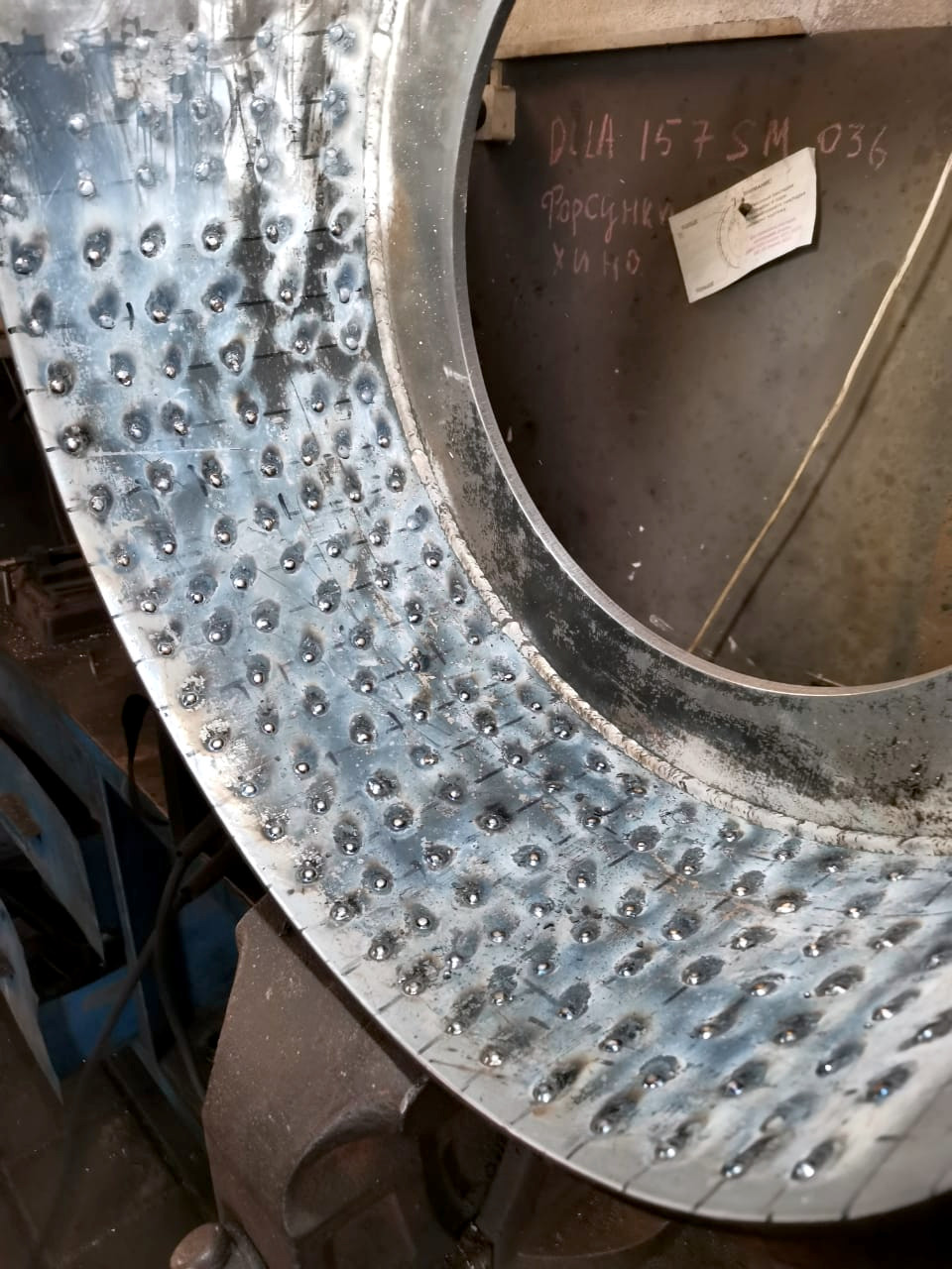 Most likely, the material intended to be fed under the rollers by blades starts sticking to them, forming clumps that slide along the inner surface of the diffuser. This happens when the material is too dry and has a low bulk density. While the diffuser surface is rusty, this effect does not occur. Over time, the surface gets polished, and clogging occurs even with moist and sticky material. There are two solutions:
- Weld drops across the entire inner surface to increase adhesion to the material,
- Weld a strip of perforated sheet, rolled to the same diameter as the diffuser ring.
Unable to Adjust the Clearance Between the Die and Rollers
If there is too much runout on the ring die track or if there is uneven wear between the rows, it becomes impossible to ensure the shells fit across the entire track width and properly adjust the gap. In such cases, either the die is sent for re-turning or a special grinding device is used, which is installed in place of the rollers directly in the pressing unit. The device consists of mounts where a straight grinder is installed on a movable carriage, allowing adjustment of the abrasive wheel's position towards the track. When constructing the device independently, it's important to ensure the grinder moves precisely along the axis of the flange shaft of the pellet mill, and the amplitude of the abrasive wheel's movement should cover the entire track width.
Uneven or Insufficient Cooling of Pellets
It means that everything was working fine before. This usually occurs due to several reasons that may complement each other:
- Wet lumps made from pellets and screenings disrupt normal movement inside the cooler, resulting in unloading only from one side. Because of stagnant places, the actual working volume of the cooler decreases, and the pellets stay in the air stream for too short a time.
- Periodic manual unloading of the cooler may disrupt air distribution when flows bypass the mass. This human factor often occurs with too small a finished product hopper volume.
- The aspiration system clogs, and the volume of air pumped through the cooler drops significantly. It's common in subzero temperatures when pumping less than 1200 cubic meters (42,380 cubic feet) per ton of pellets. Hot and humid air goes through the pipes, forming condensate and simultaneously layering dust.
- Uncontrolled unloading of the counterflow cooler. If after the drive for the unloading grid is turned off, pellets continue to flow out, it means the movable and stationary grids are aligned with the gaps between the rods. You need to adjust the displacement to full coverage so that during slow manual drive rotation, there is no prolonged spontaneous discharge in any position.
Cooler Overflow
The unloading device and filling sensors work properly, there are no drive stoppage errors, but overflow occurs with unchanged pellet mill productivity. A common reason is the damage to the knife breaking the pellets in the pellet mill. Pellets become too long, and their passage speed through the unloading device slows down two to three times.
Failure of Housing Bearings
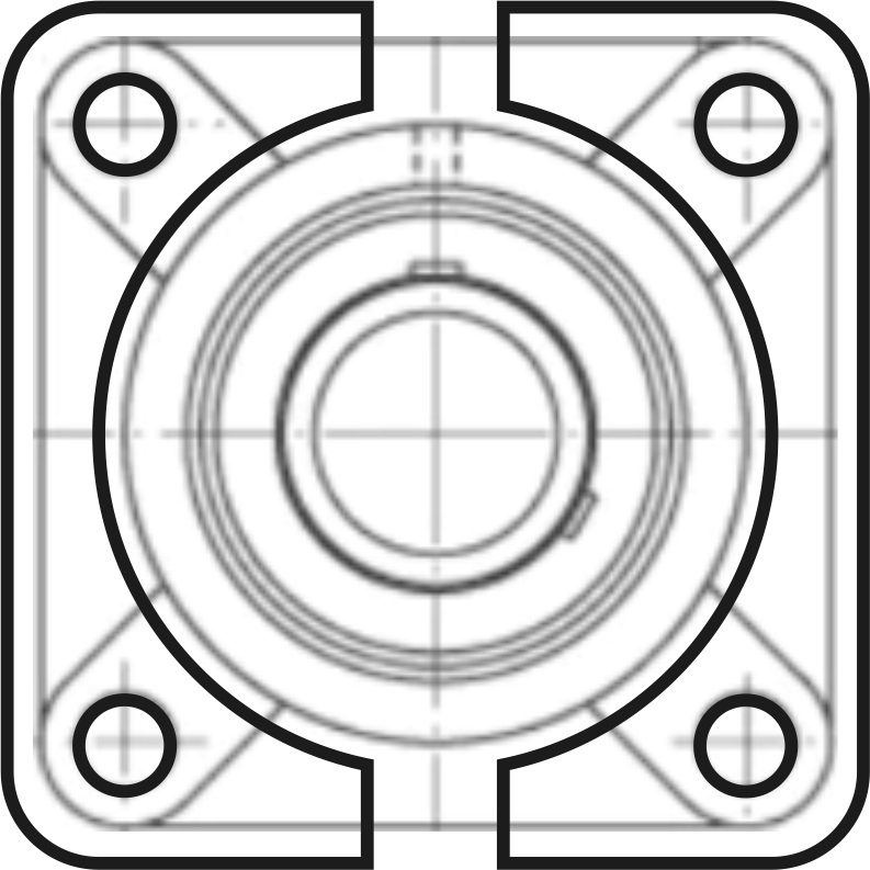 The elastic seal between the shaft and housing wears out quickly, while the labyrinth one complicates work significantly and doesn't help with significant excess pressure or steam escape, which condenses inside the bearing and damages the lubricant. To prevent dust accumulation and suction through the bearing seal, it should be installed on a 5-10 mm (0.2-0.4 inch) thick steel spacer in two halves, leaving slots at the top and bottom for free dirt discharge and possible compressed air purging before replenishing the lubricant.
Material Wrapping on Conveyor Sprockets or Drums
A very common occurrence when moving fibrous and especially wet materials with chain conveyors. The problem is solved quite simply: before the sprockets, blades need to be installed on the inner surface of the housing, which drop the material off the chains right before they engage the teeth. The phenomenon and installation location of the blades are described in detail in the section on chain conveyors.
For belt conveyors, the issue is solved using two complementary methods. First, you need to install an inclined scraper across the belt on the inner side to remove any fibers or granule pieces sticking to the belt's underside. It should be positioned to clean the bottom branch close to the lower drum. Second, it is preferable to construct drums in a design similar to a squirrel cage, where rods form the working surface instead of a solid tube. Granules that fall underneath do not damage the belt; instead, they are gradually crushed and carried along by the belt as adhered dust to the cleaning scraper.
Tearing of Stretch Film on a Pallet
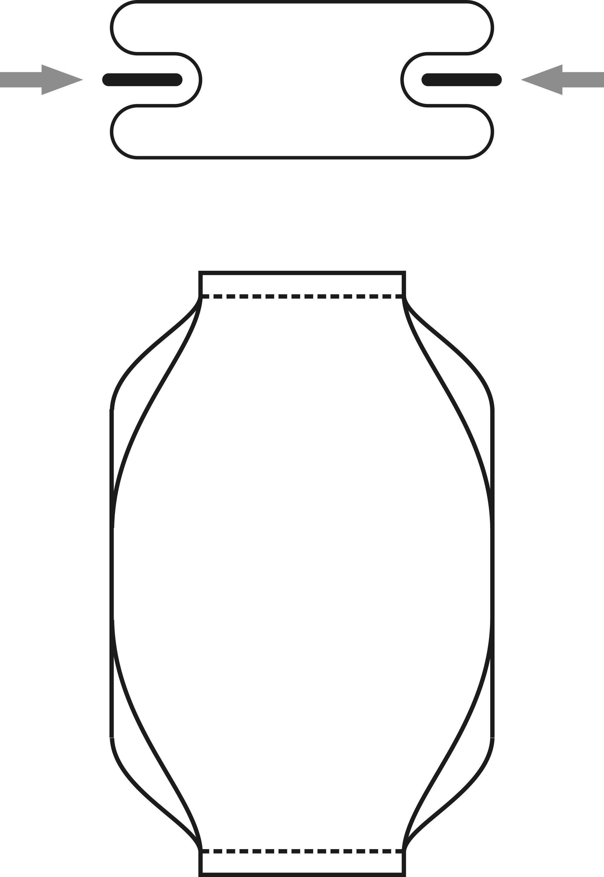 Often, in an effort to save costs, stretch film is wound around bags stacked on a pallet with tight tension. This approach is justified as maximum possible tension helps secure the bags and ensures safe transportation during multiple warehouse transfers. However, during this winding process, tearing can occur at the bag corners, requiring reduced tension, more winding layers, or additional protective strips from thick film or cloth placed at the corners. A technological approach involves tucking the edges inward at the moment of sewing or sealing the bags. Once the bag takes a horizontal position, the pellets fill the corner, creating a rounded shape. For automatic packers, this option should be added when ordering equipment. In manual packing, a simple mechanism with two paddles lowering before sealing or sewing is sufficient.
Difficulty Stacking Bags on a Pallet Due to Excess Air
When sealing bags, excess air often remains inside, causing bags to spread and roll off after stacking three layers high on a pallet. If an automatic packer does not have bag wall perforation, it should be done before stacking. In manual stacking, workers use a tool resembling a comb with 5-7 nails. A couple of taps on the bag are enough to create several holes allowing air to escape. In automatic stacking, a drum with welded nails above the last belt conveyor is used for perforating bags passing underneath. Compactly stacking bags on a pallet and covering with a top sheet closes the holes, preventing product dampness during transport and storage.
Mounting the Drive on a Platform with Two Shaft Supports
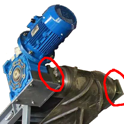 A common issue for novice designers is positioning the drive reducer on a platform attached to the machine's body while also using a support bearing close to the reducer. Tightening the reducer fixture creates substantial tension with shaft misalignment, causing fatigue cracks that cleanly slice around the drive shaft's edge over time. The most proper and reliable method is to use a standard reactive arm for such drives, allowing the entire drive mass to hang on the rotated shaft, reducing the load compared to misalignment. Platform installation is justified when connecting the drive and machine shaft via coupling, chain, or belt, and when there are no other supports for the driven shaft.
"Skinny" engines do not save money
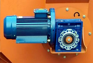 There are motors that visually appear "skinny," as if on long legs and with a long body relative to their diameter. The savings on such a drive are not significant, but they tend to heat up considerably even at 50% of their nominal load. Reducing the rotational speed through a frequency converter is almost guaranteed to damage such a specimen. These motors have installation dimensions that correspond to one frame size, but in fact, the motor is one size smaller. For example, 1.5 kW motors running at 1500 RPM are usually in the 90-frame size, and "skinny" versions also have 90 mm (4 inches) from the center of the axis to the mounting base. However, the fan cover has attachment dimensions from the 80-frame motor, which reveals its counterfeit nature. There are also more sophisticated counterfeits where a step transition between different sizes is noticeable on the cover.
Exotic Components
When designing and purchasing equipment, it is important to note and list all chain and belt drives, couplings, bushings, sprockets with built-in bearings, and other such parts and assemblies. They all transmit torque, and the failure of just one of these parts can paralyze production. The entire list may nominally be available in catalogs of nearby suppliers, but delivery time and feasibility often extend beyond the horizon of bankruptcy. If possible, stock up on spare parts, or at least ensure their availability. Additionally, check the design of these assemblies for exotic elements. A disappointing example occurred with a coupling. In the SKF catalog, it is indicated that for couplings with toroidal elements F120, the bolts pressing the rubber have a metric M12 thread. When several bolts were accidentally lost, it turned out that they had an inch thread, and it was impossible to purchase them separately, even by special order. Complete couplings were also unavailable, and alternative couplings had not been tested at these speeds and on the specific equipment. The same issue occurred with locking screws in taper bushings, but at least bushings are widely sold.