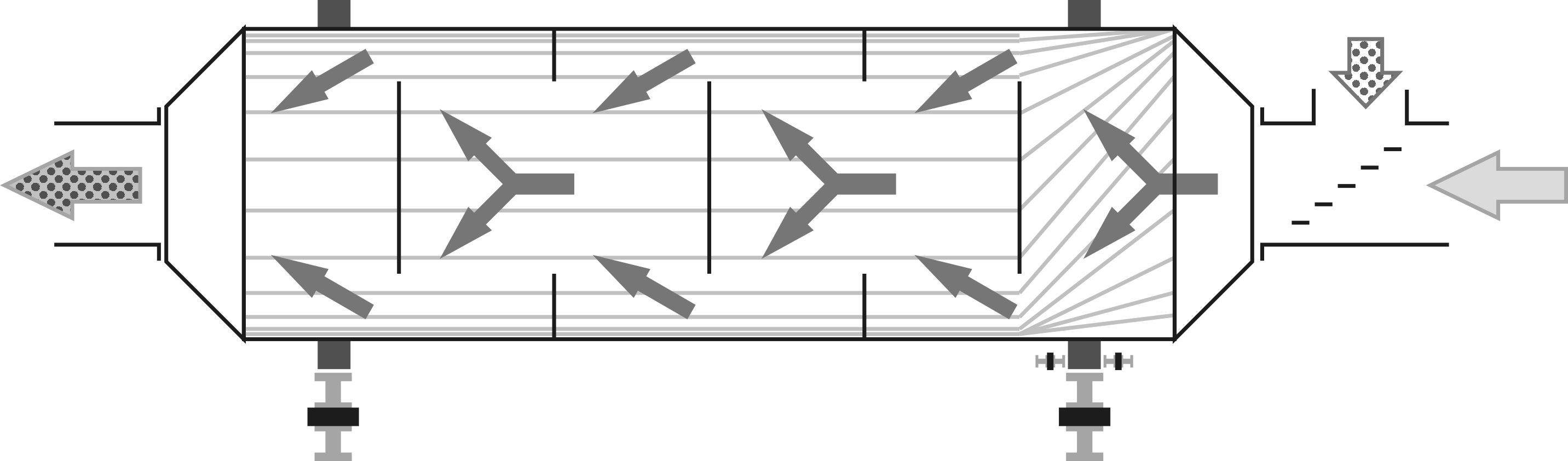
These heat generators combine the use of relatively similar furnace blocks when integrating various burners. The furnace, depending on the burner flame direction, typically consists of a horizontal or vertical cylinder, with the interior either protected by refractory brick lining or a heat-resistant steel jacket with numerous openings. In the latter case, secondary air is supplied outside the jacket, cooling it and promoting effective gas afterburning around the flame. The cost of these heat generators is two to five times cheaper than similar power units consuming raw biomass. This price difference is primarily due to significantly lower material consumption and power of the drives.
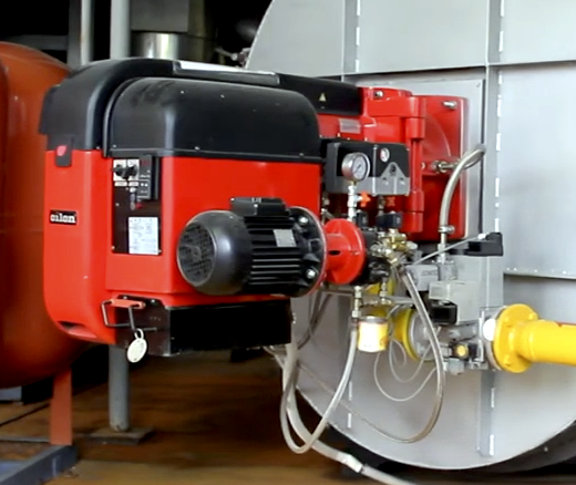
Gas Heat Generator
Gas heat generators are the most convenient to operate. The cheapest heat is usually obtained from gas burners consuming natural gas in countries with large reserves or biogas from reactors. The main combustible component in the fuel is methane, which releases minimal harmful substances with proper burner adjustment and adherence to safety regulations. To minimize carbon monoxide in combustion products, an initial burner calibration is performed, tailored to different operating conditions. The chemical composition of the gas affects its calorific value and oxygen demand, the lack of which reduces efficiency while increasing fuel consumption and emission risks.
 There are two issues in using natural gas for drying wood raw materials. First, many subsidized programs aimed at reducing fossil carbon emissions prohibit using such fuel on pellet lines. However, many countries have allowed exceptions, noting that heat from biofuel surpasses the heat for drying raw materials by five times, and the cost-effectiveness aids in successful projects in remote regions rich in wood resources. Second, gas supply and workshop connection can be prohibitively expensive in some countries. For each ton per hour of productivity, about 100 cubic meters per hour of gas supply is needed, drawing the attention of costly project companies linked to blue fuel suppliers.
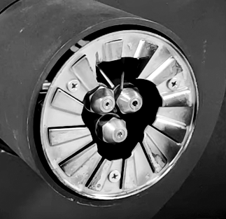
The characteristic of gas burners is the mandatory purging for several minutes after stopping. A sudden power outage leads to the automatic closure of all valves and stopping of forced draft fans. During operation, several relatively thin components inside the burner, including deflectors, remain in a red-hot state. Without purging, accumulated heat starts transferring to adjacent parts causing warping. After 10-50 such emergency stoppages, cracks appear, requiring expensive and complex repairs with a specialist's visit from the gas company, with whom a mandatory service contract is signed. To avoid such situations, all necessary delays should be programmed in the production line control automation for both shutdowns and power changes, as outlined in the burner's operation manual.
Liquid Fuel Heat Generator
Liquid fuel heat generators are typically fueled with inexpensive furnace oil, similar to diesel fuel, composed of heavier crude oil fractions. Used oils from auto repair shops and restaurants have become widely used as fuel. After filtration and settling, they can be effectively burned in specialized burners of two types based on the fuel atomization method: fuel oil burners with a high-pressure hydraulic pump and ejector burners with air atomization.
Both types usually include an operational tank with heating, a photocell for flame monitoring, startup automation, and signals for starting the supply pump. The distinctive feature of an oil burner is that atomization occurs due to the relatively high pressure in the nozzle, usually 20-30 bar (290-435 psi). For such pressures, a simple and reliable centrifugal pump is not suitable, and instead, gear, plunger, or vane pumps are used. All high-pressure pumps are manufactured with high precision, and the ingress of water or solid particles quickly renders them unusable. For instance, the gap between the plunger and cylinder in a plunger pair is only 10-15 microns, and even for fairly quality filters, a particle size of 10 microns is the limit for filtration capability. Nozzles at such high pressure also react adversely to contamination: mineral particles lead to accelerated wear of the atomizers, and dirt can layer on internal surfaces, disrupting normal atomization and requiring regular rinsing and cleaning. Therefore, the operational life span of oil burners using low-quality fuel is short, and repairs are expensive.
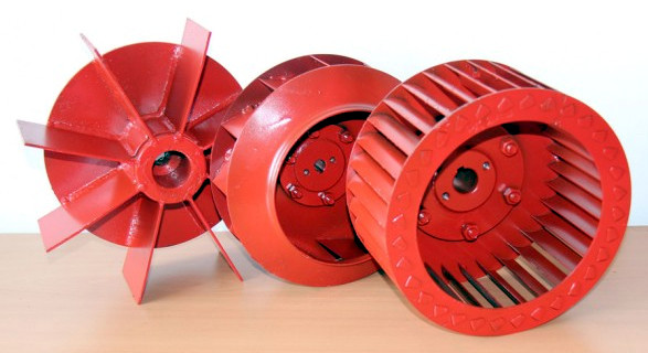
 Ejector burners are significantly cheaper, as the fuel is drawn into the nozzle and atomized by a stream of compressed air. Secondary air is supplied by a regular fan and swirled by a swirler, promoting active mixing of flows within the flame and complete combustion of the oil mist. The diameters of the tubes and atomizers are selected so that when the air supply pressure varies from 0.2 to 2 bar (3 to 30 psi), the liquid fuel flow changes proportionally, ensuring smooth adjustment of thermal power. It's important to note that for 1 MW of thermal power, liquid fuel consumption may reach up to 100 liters (26.4 gallons) per hour, and 600-700 liters (160-190 gallons) of compressed air per minute is required at a pressure of 2 bar (29 psi), which can be provided by a compressor with at least 11 kW (14.8 hp) power. Considering continuous operation, screw compressors are preferred due to their greater reliability over their lifespan and their 1.5 to 2 times higher efficiency compared to piston models.
Special attention should be given to the pipes between the compressor and the burner. Often, when installing new equipment, existing communications are used, including compressed air lines distributed throughout the workshop. A basic calculation shows that with a compressor pressure of 8 bar (116 psi) and a tube length of 10 meters (33 feet) with a diameter of 8 mm (0.3 inches), the required 150 liters/min (39.6 gallons/min) at 6 bar (87 psi) will reach a pneumatic wrench. However, attempting to pass 1000 liters/min (264 gallons/min) at 2 bar (30 psi) through a 15 mm (0.6 inches) pipe will result in a 70% pressure drop and not enough for the full power of the burner.
For continuous feeding of a 1 MW liquid fuel burner, it is optimal to use a pipe with at least a 20 mm (0.8 inches) diameter when the compressor is installed within walking distance. The relationship between pipe size and pressure losses is quadratic, so for an installation four times more powerful, simply doubling the diameter is sufficient to freely pump the necessary amount of air.
Pellet Heat Generator
Pellet heat generators are usually lined with firebrick internally because embers and ash often eject from the burner, accumulating and adhering to the walls. Cleaning intricate stainless steel screens is more likely to cause them to warp than when using refractory brick. Another reason for the massive furnace is integrating the pellet burner into a solid fuel block initially intended for burning wood, coal, or other large chunk fuels.
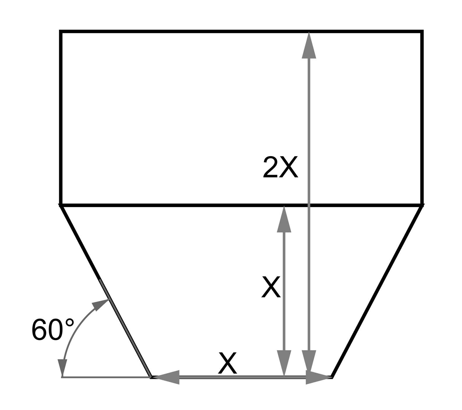
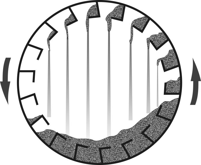
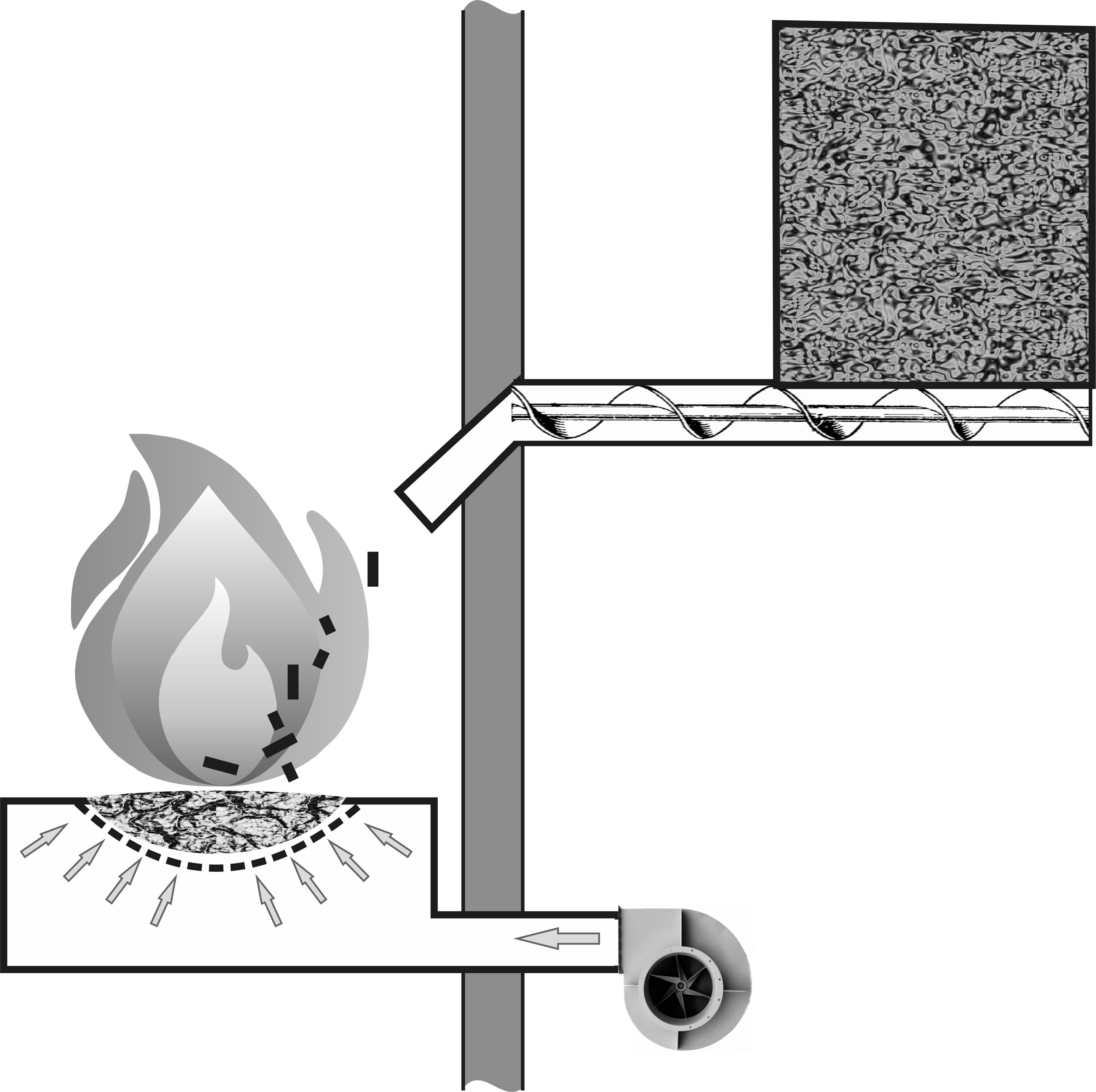
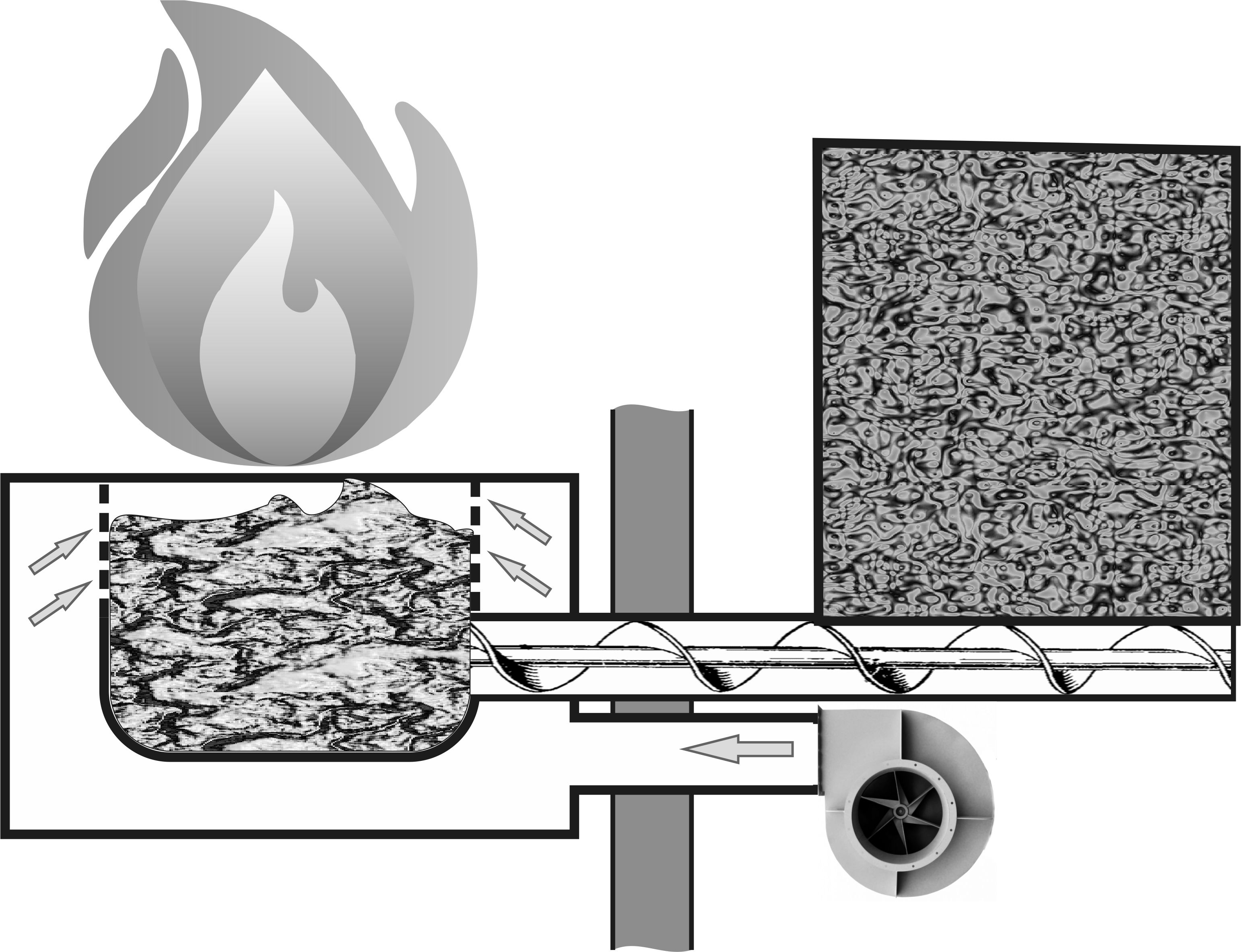 In terms of design, pellet burners are quite similar to chip furnaces and are also roughly divided into retort and torch types, analogous to pyrolytic and staged heat generators, respectively. In retort burners, pellets are fed from below, shielding the basket from overheating, while air is blown around the perimeter of the pile, causing surface combustion and pushing the pyrolysis front deeper as it meets the flow of pellets. In torch burners, the pellet layer is small, and the ventilation intensity is high, which prevents the basket or grates from overheating. In torch burning, pellets are typically fed from the top in small portions, rolling down a tube aimed at the burner's center. The guiding tube usually does not enter the combustion space but simply sets the angle of descent and initial velocity, hoping for a parabolic trajectory.
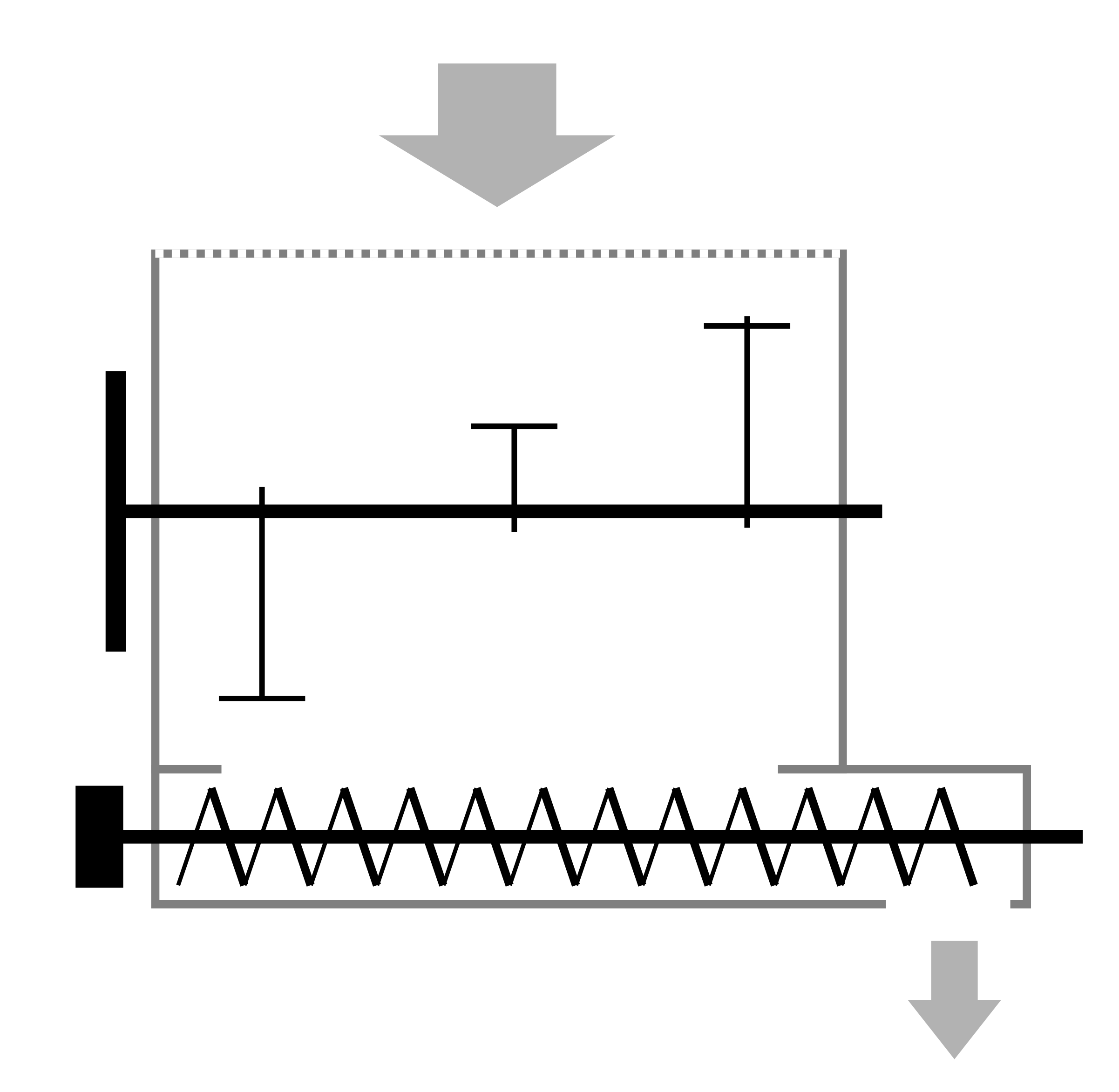
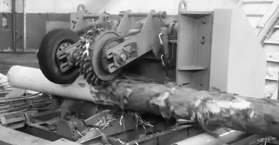
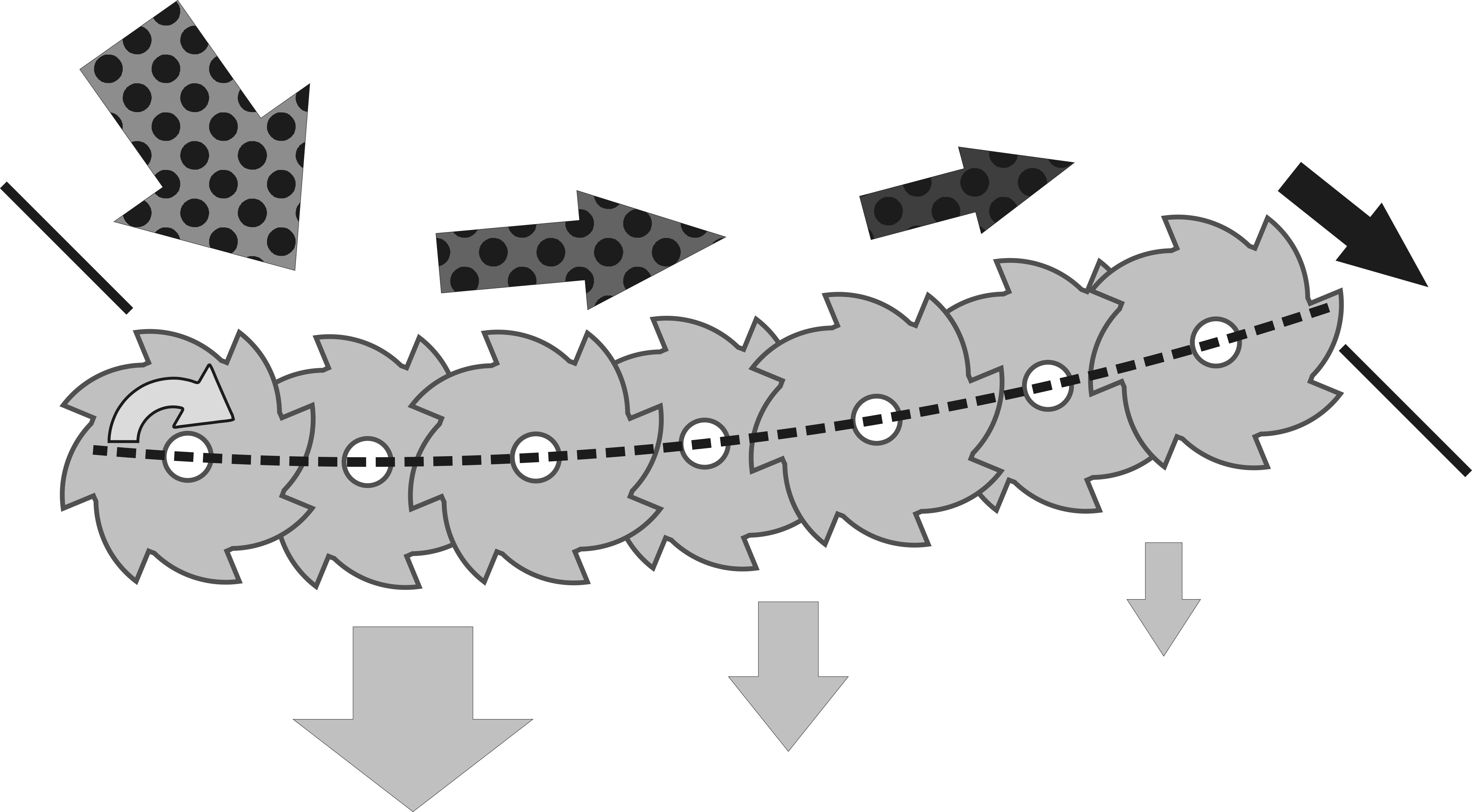
 Burning a thin layer of granules helps blow ash off their surface, which settles around the burner and needs periodic clearing, unless specific mechanisms are in place. For working with high-ash or just dirty granules, and pellets with a low ash melting point, moving grates of a scalene type are used, similar to those for raw chips, or a miniaturized version of a disc separator is employed.
Pellet burners are configured similarly to gas ones: the speeds of the feed augers and the ventilation fans are set in 10% power increments. Since the supply dependencies of both components are far from linear and rely on individual construction features, the controller has several modes depending on the pellet diameter, calorific value, and origin. This means setting up is done in test mode with high-quality pellets, and an operational mode is selected with adjustments.
The use of pellet heat generators in pelletizing lines is quite debatable. One undeniable advantage is the ease of operation comparable to a gas burner with its consistently delivered power and control, without dependence on fossil fuels. The downside is that pellets are an already finished product that can be sold at commercial prices instead of being burned at cost. There are two approaches to calculations here.
The first approach is subtraction. To produce 1 ton of pellets, 1 ton of water must be evaporated, requiring the heat generator to produce 1 MW of power for 1 hour, consuming about 200 kg (441 lbs) of pellets. With this calculation, the output is only 800 kg/h (1764 lbs/h) of product with a production line capacity of 1 ton per hour. The second approach involves a comprehensive calculation of costs and profits without isolating part of the raw material as fuel. In this method, comparison is typically made with a more expensive heat generator for wet fuel, which requires significantly more auxiliary mechanisms, while moisture and fraction variations reduce the daily average productivity of the line and the overall quality of the pellets. With the second calculation method, pellet burners are advantageous for pelletizing lines with a capacity of up to 2 tons per hour.
The drawbacks of pellet heat generators appear with high initial moisture content in the raw material. For example, at 70% moisture, the dryer's capacity will be halved, and nearly half of the product will be used for combustion in the heat generator. Thus, following the subtraction approach for a 1 ton/hour line, the dryer output will be only 500 kg/h (1102 lbs/h), while pellet consumption remains 200 kg/h (441 lbs/h), reducing the product output almost threefold. If this situation were applied to a pelletizing line with a wet chip heat generator, fuel supply would increase to maintain power. The pace of pellet production would only decrease due to the dryer's capacity limitations, meaning the net output would be 500 kg/h (1102 lbs/h). This is why pellet heat generator lines have not been widely adopted in the harsh conditions of Russia.
Another disadvantage of pellet burners is the risk of sudden power outages. Pellets smolder for 10 to 30 minutes after the fans are turned off, depending on the retort's volume, and the gravity feed implies placing the fuel hopper above the burner. Therefore, if the fuel hopper becomes unsealed, there's a significant risk that flames or hot gases from the smoldering pile will be drawn into the feed channel and ignite the fuel. A basic protective measure is installing a thin transparent polyolefin hose in a break in the steel pipe, which melts quickly in case of a fire, releasing the pellets outside. The remaining handful smolders and descends into the burner, preventing a fire. Sometimes, fans installed close to the hot zone suffer during such smoldering since they can also allow backflow of hot gases.
There are many fashionable passive and active protection types for sale: sensors with autonomous power, carbon dioxide systems, ampoules with special liquid... Such passive protection can be easily fabricated from readily available materials. It is sufficient to weld a ½-inch threaded nozzle onto the auger or guiding tube. Separately, prepare a coupling in which wax is poured to a 20-30 mm (0.8-1.2 inch) thickness approximately in the middle. To get the wax plug in the middle, the molten wax must be poured while the coupling is submerged in water up to almost halfway. Then, the coupling is screwed onto the nozzle, and its second end is connected to a container with water or a non-freezing fire-fighting solution. When the coupling heats to above 80°C (176°F), the wax melts, allowing all the liquid to enter the auger cavity, reaching the source of heating. It's advisable to stockpile 5-10 of these couplings with wax plugs along with spare parts, so workers do not neglect protection.