 The toothed surface of the track has become the most popular because it is the simplest way to use ordinary gear cutting machines intended for gears. In order to order the tool for this, it is enough to specify the tooth module and the diameter the cutter needs to penetrate.
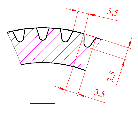
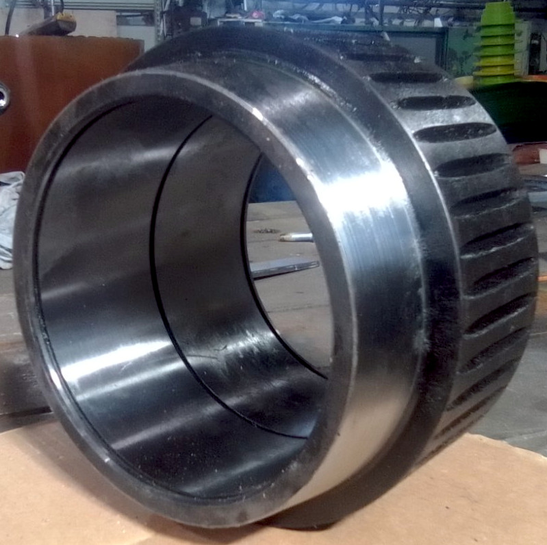
The difference from a gear is that no complete teeth are cut. Attempting to use a gear results in rapid tooth breakage due to excessive lateral pressure. A reliable formula for the grooves is that the gap between the surfaces of the teeth and the depth of the grooves should be approximately the same, while the width of the tooth surface should be about 1.5 times larger. Essentially, the gear is cut only to about 50-60% of its classic form. The drawing shows an example of groove dimensions for a 3 mm tooth module, although end rings with grooves from a 2.5 mm tooth module are more popular and versatile.
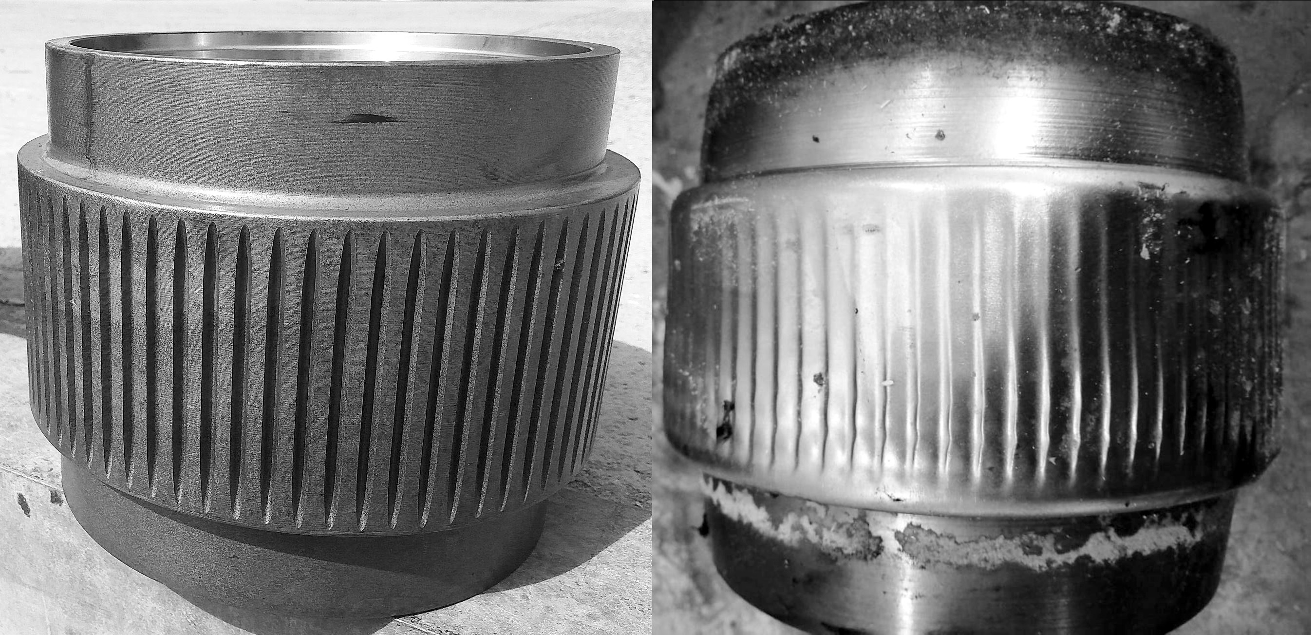 The shell wears not only on the surface in contact with the die but also between the teeth as metal is washed away by the material. As a result, the teeth become sharpened, pushing the material into the dies with much less efficiency. The ability to capture new portions of material also decreases, leading to reduced productivity. Lateral ejection of material between the grooves can be partially mitigated by not making the grooves extend all the way to the edge of the track, leaving 2-5 mm (0.08-0.2 inches) smooth edges. Applying curved grooves also solves this problem but significantly complicates and increases the cost of manufacturing shells because CNC milling machines are required. Sometimes, to combat lateral ejection, grooves and drillings are combined, arranging the latter in 1-2 rows along the track edge.
 The lifespan of the shell directly depends on the tooth size, which prompts the creation of shells with an 8 mm (0.3 inches) tooth size, produced using a 5 mm (0.2 inches) cutter module. These shells have indeed shown double the lifespan, but two significant drawbacks were also identified. First, "chewing" of the material before pushing it into the dies increased sharply. The layer of actively mixed and ground material increased at the same productivity, leading to a sharp increase in load on the pellet mill's drive and excessive electricity consumption. Second, the lateral ejection of material between the grooves increased to such an extent that it accelerated the wear of the die track by 2-3 times. The wear was much stronger at the edges, and the uneven gap between the shell and the die worsened the situation. As a result, after experiments with different module sizes in biofuel production from various raw materials, producers moved from a 2.5 mm module to a 3 mm module, which, according to most equipment operators, is considered optimal for producing 6 mm (0.24 inches) and 8 mm (0.31 inches) diameter pellets from wood or sunflower hulls.
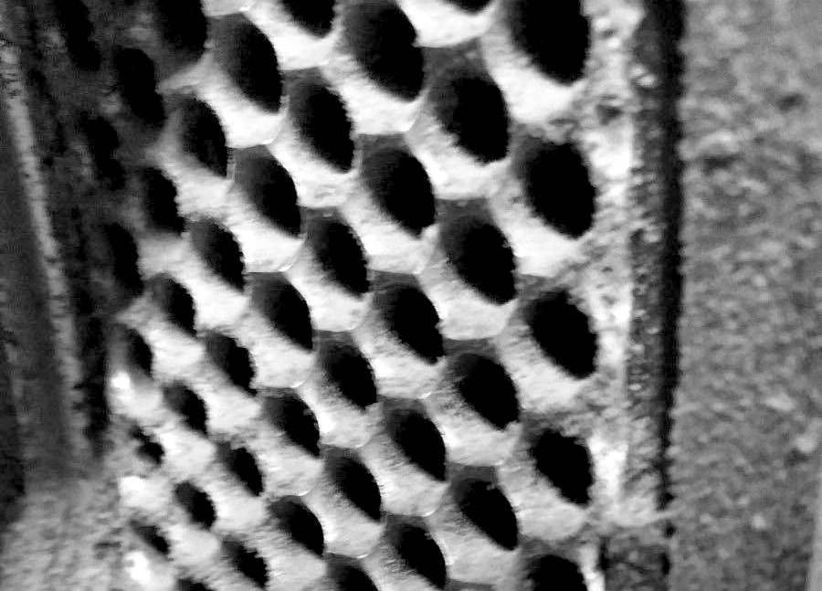
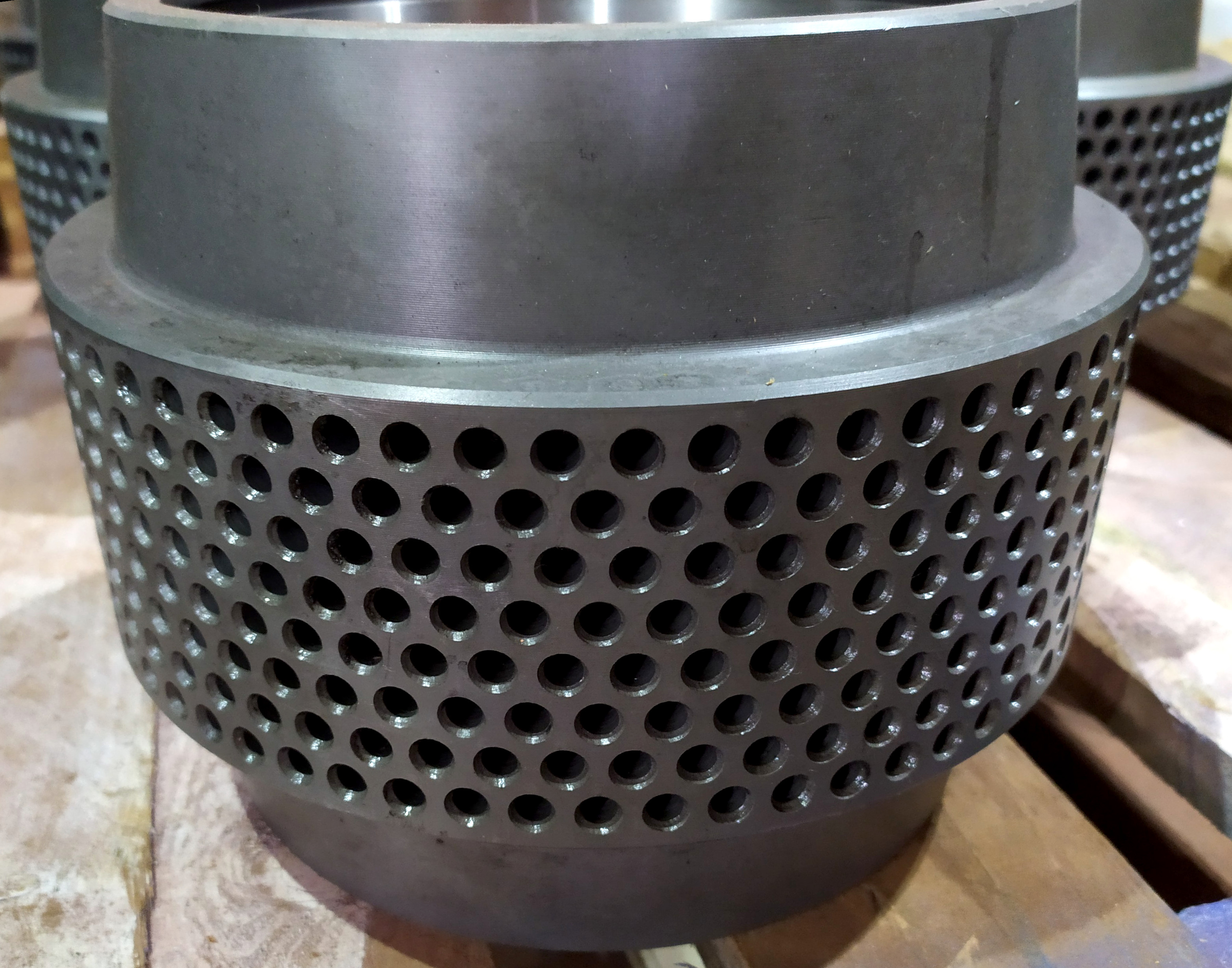 The pressure created by the tooth can be 2-3 times greater than the average pressure on the material layer at the contact spot of the rollers with the die. The indentations help achieve maximum compression, which happens gently over several passes of the roller over the material. As it turns out, irregularities of any shape have a similar effect. Shells with surfaces drilled to a depth of 5-10 mm (0.2-0.4 inches) have become quite common. The diameter of the blind holes is selected similar to the size of the tooth: too large a diameter will lead to excessive electricity consumption, while too small drillings will make the product significantly more expensive. The drilling is done on the same CNC multi-spindle drilling machines used for making dies. Therefore, this configuration is usually not more expensive than applying indentations.
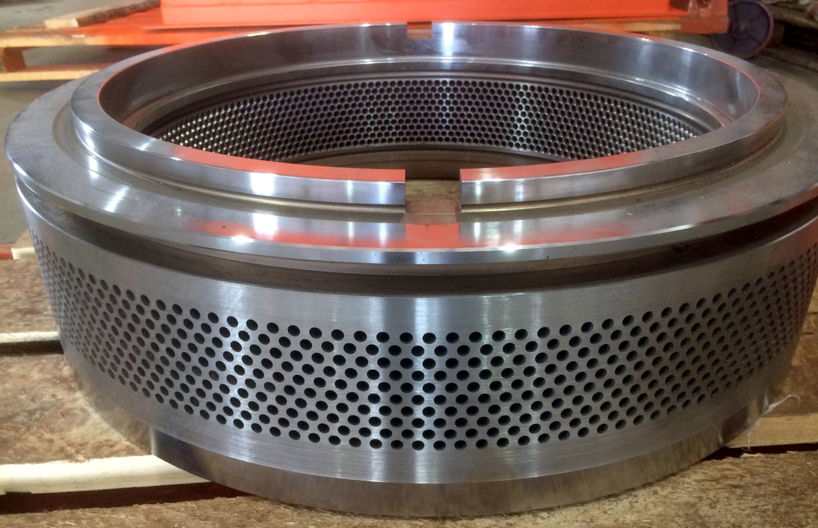
The perforated surface has two significant advantages. First, the surface profile does not change as it wears, which is common with teeth. There is no washing out in the depressions; instead, they fill with material and create self-lining, reducing wear. Second, the depth of the depressions is not limited by the size of the tooth. If the design allows, the traction layer under wear can be 2-3 times thicker, greatly extending the overall service life. The main downside of such a surface is the inability to hire employees with trypophobia.
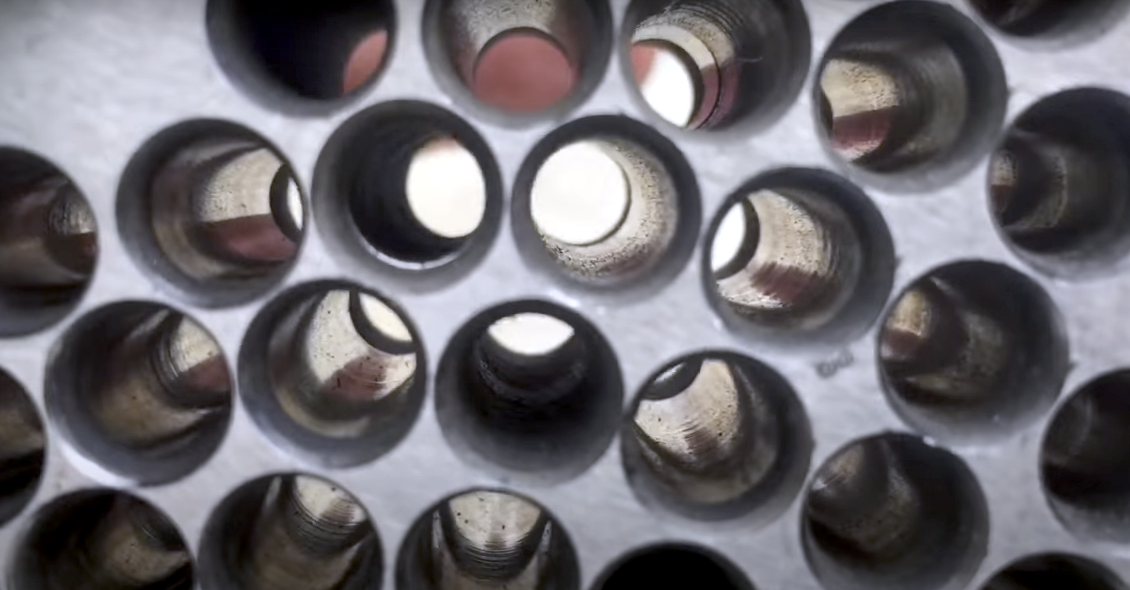
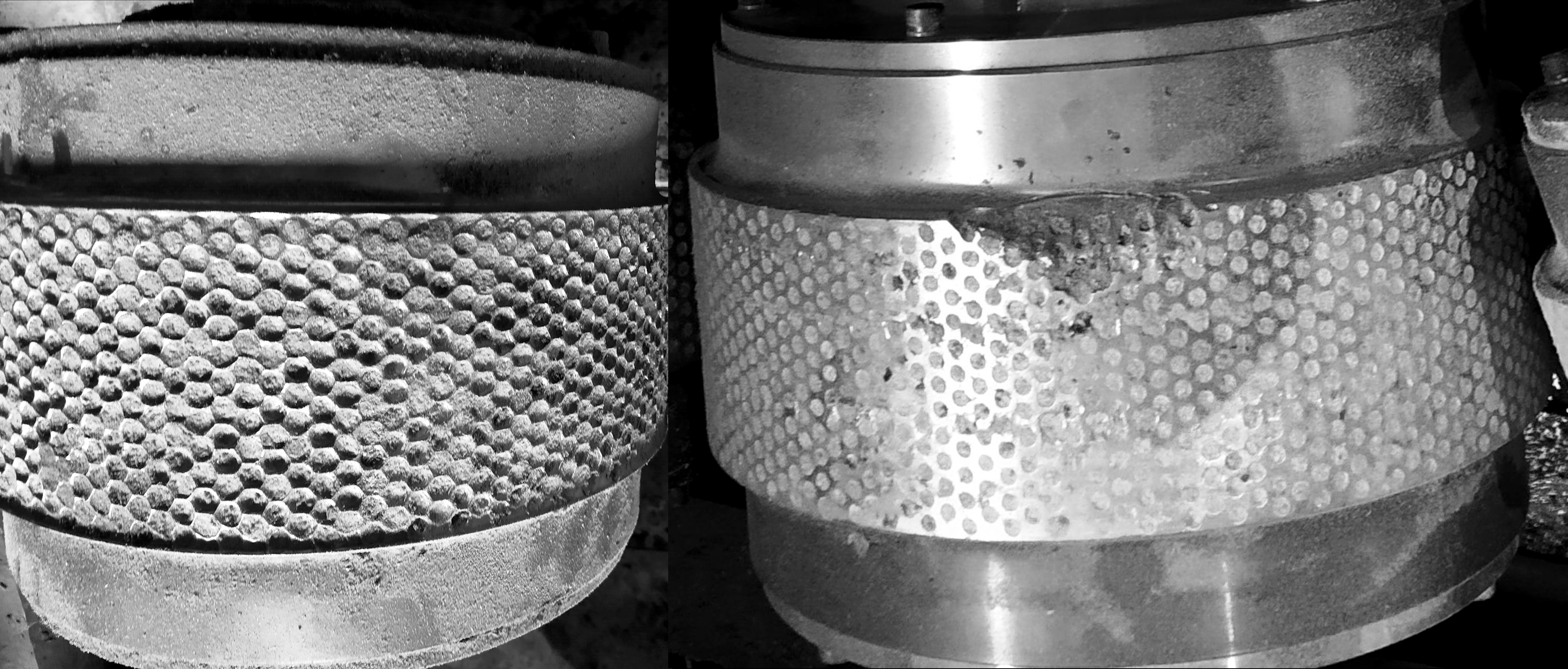 It seems that selecting the diameter and spacing between holes is as simple as using a ready-made solution: arrange them similarly to the holes in the die. Too far apart will reduce productivity, and the operation will resemble a worn-out condition. Holes too close together make the bridges thin and weak, leading to rapid destruction, similar to the attempt of using high gear-like teeth. Reducing hardening hardness somewhat protects against chipping but accelerates wear and flattening of the track profile. The decision regarding the selection of diameter and spacing between the drillings on the shell track is simple: arrange the holes like those on the die, with the drilling diameter being 20-25% smaller and adding a sufficiently deep countersink with a 90-degree angle.