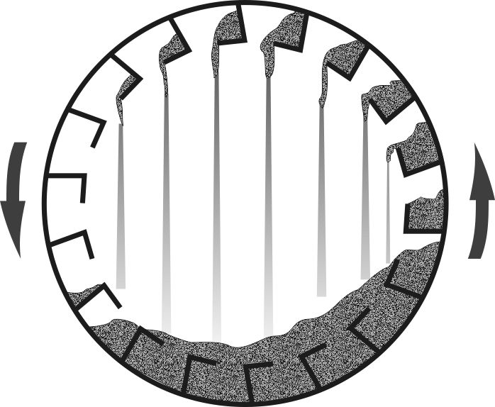
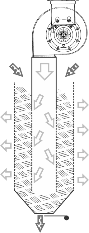
 The working principle of the louver cooler is taken from a similar device that cools grain from a field grain dryer. Its construction is simple: grain is introduced between two vertical perforated tubes, and air is blown into the inner tube, passing through the grain layer to the outside. Discharge is accomplished through a funnel with a gate to regulate material flow. Pellets can also be cooled this way, but the expelled air will contain a lot of dust, and ungrouned parts will fall through the perforated sheet.
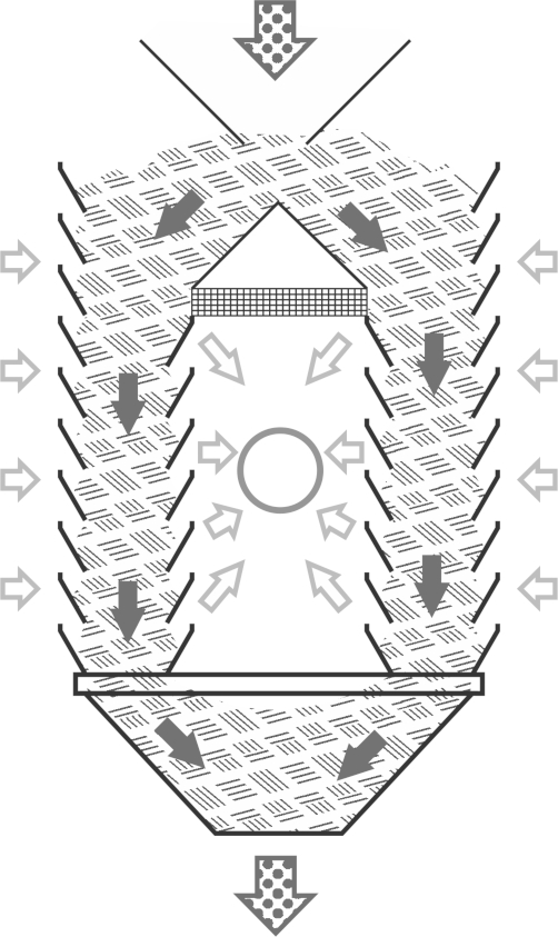
In a louver cooler, air is not blown in but extracted from the inner cavity. Fresh air is drawn in from outside through panels made like slanted louvers. The slanted plates allow nearly free air passage but prevent pellets from spilling out. Unloading is done either by vibrating a sieve under the lower funnel outlet or with a swinging gate.
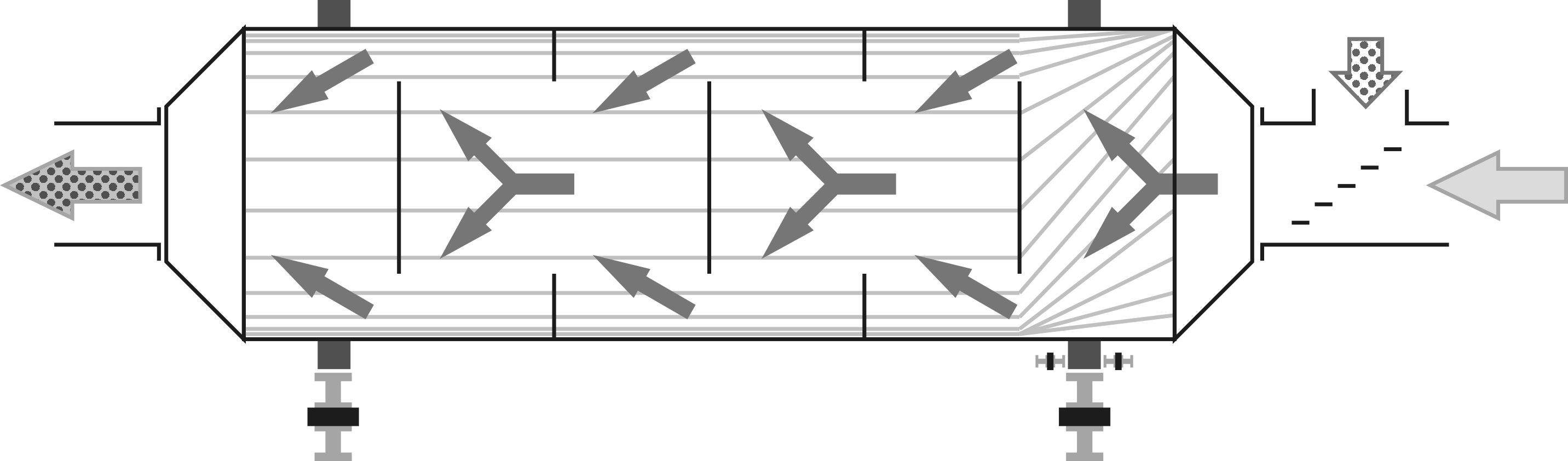
 Rectangular section louver coolers, where two rectangular parallelepiped-shaped cavities are separated by a cavity with reduced air pressure, have become widespread. Their capacity usually ranges from 1-2 tons per hour. Much more compact designs are possible with coolers that have square cross-sections for both the outer perimeter and the inner cavity, similar to grain coolers but using louvered panels. This configuration allows for relatively inexpensive pellet coolers with a capacity of up to 20 tons per hour that fit within transport dimensions when assembled. The distance between the inner and outer louvered panels is only 0.25-0.35 meters (0.8-1.1 feet), so the slanted surfaces of the plates bear most of the weight of pellets. The pellets effectively get stuck between the louvers with minimal bottom resistance, eliminating considerable hydraulic pressure at the lower cooler parts, even with a column height of 7-8 meters (23-26 feet).
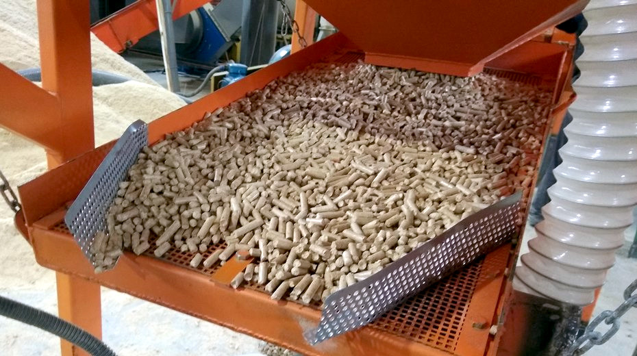
It should be noted that the inner cavity has no bottom, allowing any accidentally trapped pellets or particles to exit through the lower edge into the main mass. The top row of louver plates on the cooler's inner side can be beneficially replaced with a piece of perforated sheet. During the initial column filling, when there are 1-2 gaps above the pellet pile, the air flow through them can be too rapid and can lift pellets into the aspiration system. The screen stops the pellets and usually self-cleans from stuck particles during further operation, as airflow slows to normal speeds and incoming pellet batches scrape off residues.
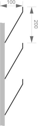 Fabricating the internal part entirely from perforated sheet is not recommended as pellet slide is uneven, leading to jams and potentially wet clumps forming. Using perforated sheet is not cost-effective, as the cost per square meter with reinforcing frames is roughly equal to louvers made from 2 mm thick rough steel plates. This holds true if the louver pitch is 200 mm (8 inches), and panel thickness, including the metal profile joining the plates, is about 100 mm (4 inches).
The filling sensor in the cooling column is placed to consistently maintain a pellet layer thickness of 0.3-0.5 meters (1-1.6 feet) above the inner space to prevent louvre plates from being exposed. If the timer relay setting is too long, exposing the inner structure leads to airflow redistribution, and air bypasses the pellets, sharply reducing cooling efficiency. Cooling of the pellets starts immediately from the top with fresh air, so sticky pellets quickly release initial moisture, and the rest of the time is primarily focused on cooling rather than drying.
 The advantage of a square section louvre cooling column is its simplicity, particularly the absence of a rotary valve at the entrance and a special discharge device at the exit. It effectively forms a vertical pile of pellets from which hot moist air is extracted from the center. A symmetric funnel shaped like an inverted pyramid ensures even unloading from all sides, and a sieve can be placed directly under the narrow exit without additional mechanisms or gates. A sufficiently thick layer of pellets constantly stands between the exit and the internal space, effectively sealing off air entry. Therefore, the pellets themselves act as a valve. Spontaneous spilling does not occur, as the forming heap on the fixed sieve halts unloading, similar to an automatic bird feeder made from a tray with an inverted bottle.