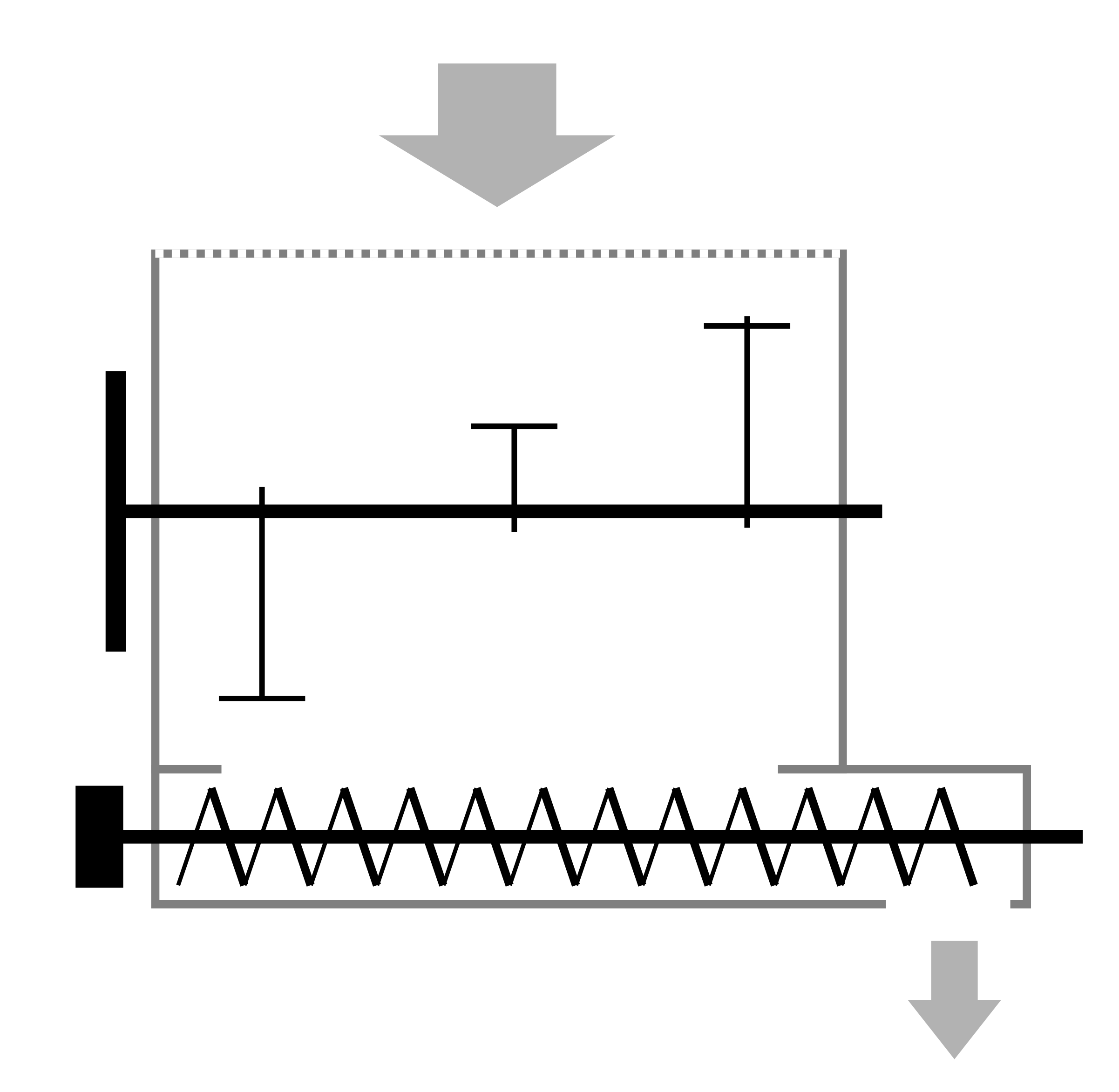
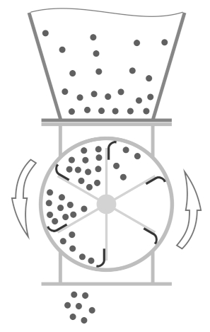
 This is a very popular device used with cyclones, allowing the discharge of bulk materials from pressurized hoppers and equipment chambers. Its operating principle is simple. The tightly fitting rotor blades allow minimal air leakage through the gap, while the material is carried in the spaces between the blades to the lower exit. The blades are either precisely fitted to the housing, used for finer and abrasive materials, or equipped with elastic strips for sealing around the entire perimeter of each blade.
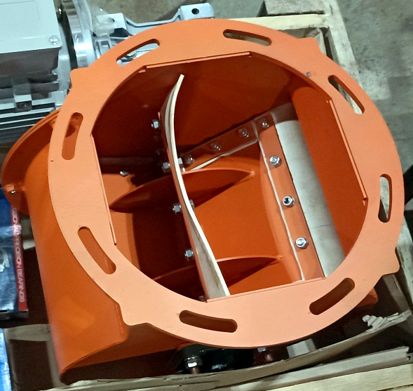 Since biomass fuel materials tend to be relatively bulky, a clearance of 30-50 mm (1-2 inches) is left between the steel blade and the housing, and sealing is achieved using pieces of rubber conveyor belt or more heat-resistant and soft silicone plates. Due to the remoteness of such production facilities, sealing plates can also be made from materials like pieces of polyethylene containers and other relatively wear-resistant elastic materials. A slight bend in the seal is sufficient for tight contact with the housing. Otherwise, the edge bouncing upon exiting the upper opening can cause material blockage in cyclones. With proper equipment operating conditions, heat resistance is not a concern, as reheating does not occur due to the cooling effect of the passing material.
The performance of a rotary airlock valve is calculated relatively simply. Calculate the volume of the cylinder that houses the rotor, then multiply it by the number of rotations per hour and the bulk density of the material. Given that the rotor usually fills no more than a third due to bouncing seals, particle drift, and volume-preserving stiffeners and hardware, divide the result by three. For example, a rotary airlock valve with a rotor diameter of 300 mm (12 inches) and a width of 200 mm (8 inches) has a volume of approximately 14 liters (3.7 gallons). At 30 rpm, considering a third of the volume filled, it will deliver about 8,400 liters (2,220 gallons) per hour, which at a sawdust density of 200 kg/m³ (12 lb/ft³) equates to only 1.7 tons (3,700 pounds) per hour.
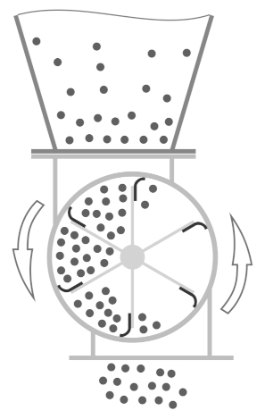 The simplest way to increase the valve's performance is to increase the RPM. For free material entry, centrifugal acceleration at the blade edges should not exceed half of the gravitational acceleration. For the mentioned valve parameters, acceleration is about 1.5 m/s² (4.9 ft/s²). So, to increase performance, you can increase the rotation frequency by 1.5-1.8 times, achieving centrifugal acceleration of 3.3-4.8 m/s² (10.8-15.7 ft/s²) at 45 to 54 rpm. Further speed increases will significantly reduce rotor fill. At 45 rpm, blades pass through the upper nozzle every 0.22 seconds, allowing material free fall for only 240 mm (9 inches) without accounting for drift, just reaching the rotor shaft. Valves with offset inlet and outlet nozzles along the rotation path achieve double the capacity at the same size because the blades help capture the material and prevent backward ejection, allowing for a 1.5 times increase in RPM with better fill. Increased RPM with this design improves rotor discharge through the lower nozzle due to material ejection with acceleration.
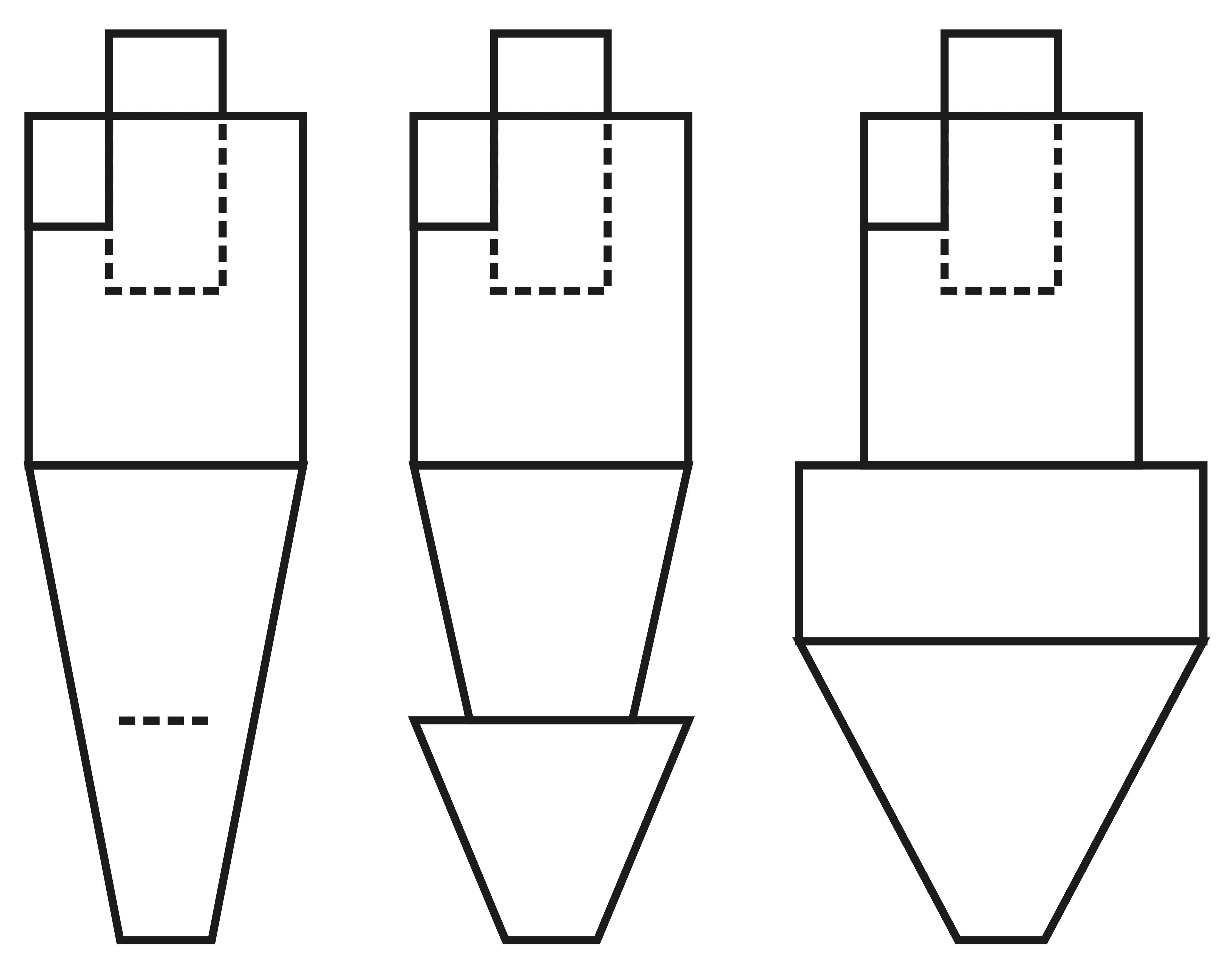
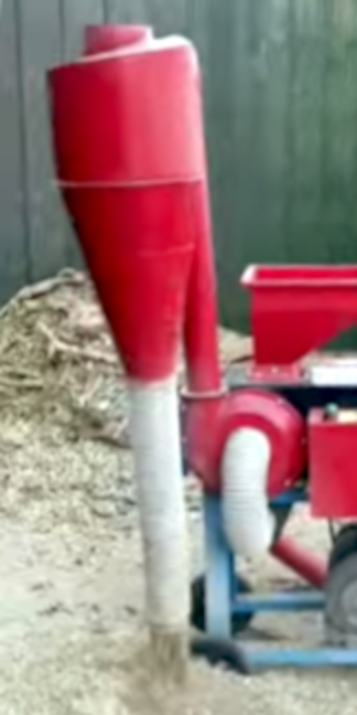 A basic alternative to a rotary airlock can be a piece of regular corrugated flexible tubing. Since the rotation of air in a cyclone creates a noticeable vacuum near its axis, the excess pressure of the air being injected into the cyclone is partially compensated, and only 20-30% of the total volume exits through the lower flange. The corrugated hose facilitates a smooth fallback of the material, with its particles serving as an additional obstacle to the airflow. The diameter of the corrugated hose is usually half the diameter of the cyclone’s upper flange, and the hose's length is 4-5 times its diameter. Ultimately, the diameter and length of the hose are selected individually so that during operation, the material covers 2/3 of the corrugated hose's cross-sectional area. This provides a slight margin to prevent the formation of clumps at the cyclone's exit.