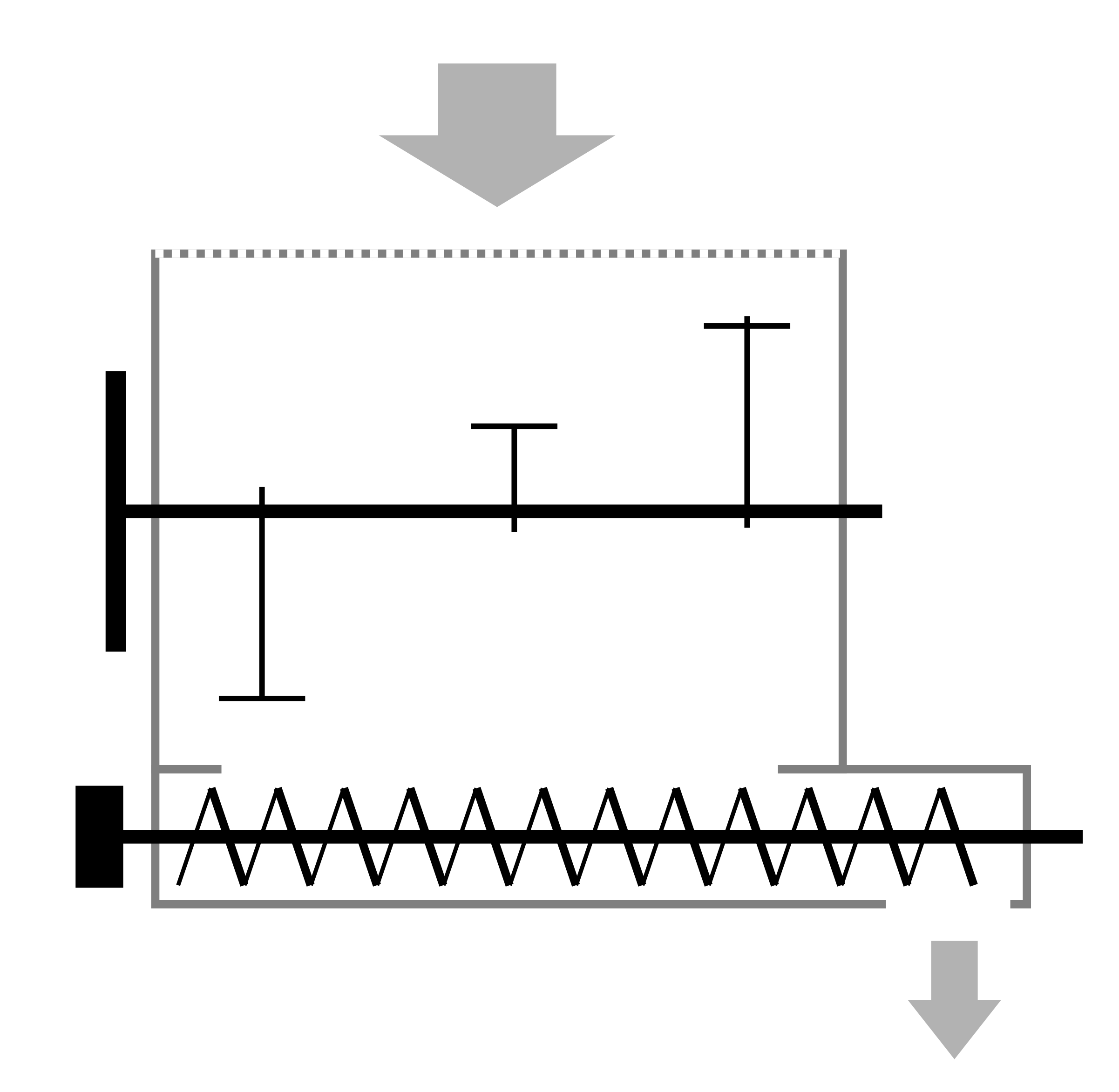
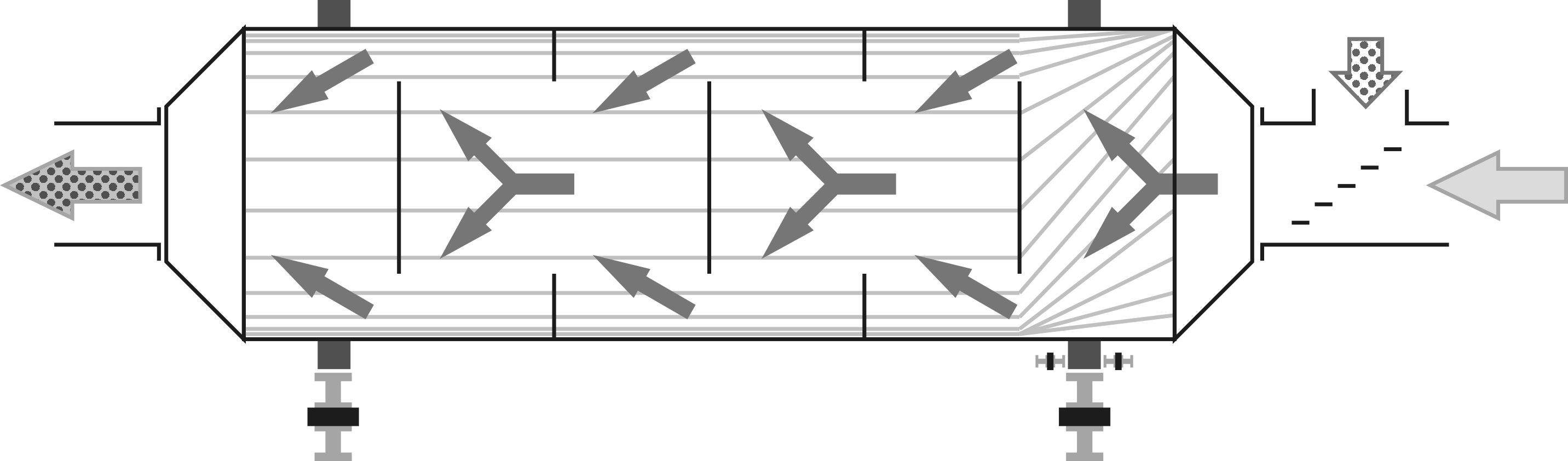
Another way to combine transportation and drying is to introduce hot oil or steam into the hollow shaft of a screw conveyor. The screw has much more contact area than the housing, and in a U-shaped design, the material is well mixed. The screw shaft should be made as a double pipe: steam reaches the driven end through the inner pipe, and on the way back, it heats the spiral turns through the outer contour, moving counter to the material and enabling counterflow heat exchange. As sawdust dries, it loses its stickiness, so the spiral turns won't require cleaning, but for materials that are initially sticky, you need to check the temperature settings in advance.
When designing a dryer based on a screw conveyor with an oil heat carrier, the scale required to transfer such significant heat volumes is often underestimated. If using a temperature difference of around 100°C (212°F), such as reducing from 250°C (482°F) to 150°C (302°F), about 400-500 liters per minute (106-132 gallons per minute) are needed to transfer 1 MW of heat. This temperature setting prevents overheating above 300°C (572°F) due to volatile substance evaporation and coking, and below 100°C (212°F) to avoid a sharp decrease in moisture evaporation intensity. Since even fluororubber seals operate up to 200°C (392°F), it's advisable to initially pass the flow through the conveyor housing and then into the screw shaft, or alternatively, reduce the temperatures.
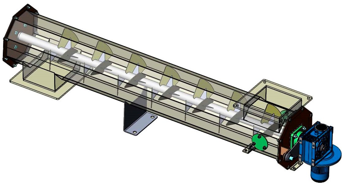
The surface area for heat exchange, pertaining to both the screw housing and the shaft, is determined to be one square meter (10 square feet), for every 10 kilowatts of heat transferred. Hence, to transfer heat only through the spiral of a screw with a diameter of 250-300 mm (10-12 inches) and the wall of the hollow shaft, around 10 conveyors of 5 meters (16 feet) each are needed, arranged one above another in pairs, or similarly paired in five double housings similar to a twin-shaft mixer for feed. The interlocking flights of one screw between the turns of an adjacent one will aid in self-cleaning and better mixing, with the spiral winding and rotation in opposite directions to prevent material build-up on one side of the trough. Adding heating to the housing reduces the number of conveyors by half. Providing the conveyors with heat carrier in a parallel scheme reduces the pressure needed to circulate relatively viscous oil, especially during the startup of the dryer until reaching working temperatures. It's quite safe to use centrifugal pumps with a maximum pressure of up to 3 bar (44 psi), which is enough for a smooth warm-up of the system at low flow due to viscosity, and meanwhile allows using regular plumbing pipes to lower construction costs. The pump power for a 1 MW dryer ranges from 5.5 to 15 kW, depending on the distribution system's complexity and ultimately the mainline length with the number of turns.