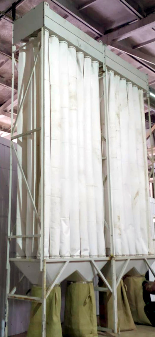
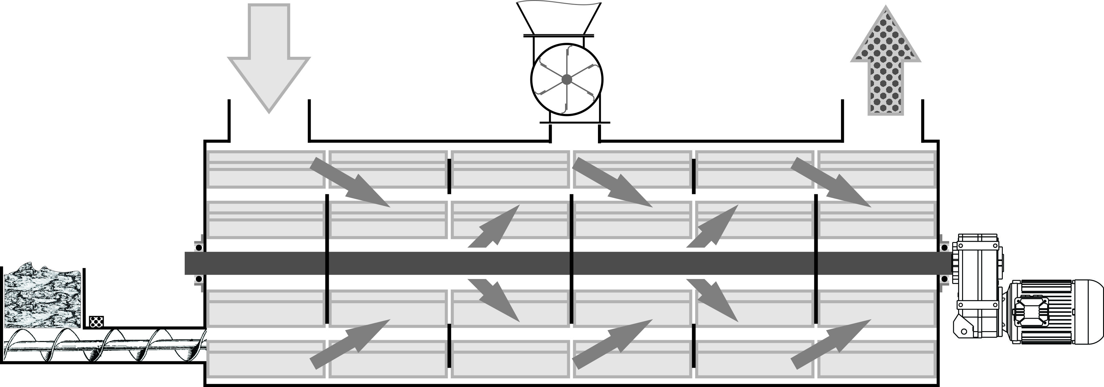
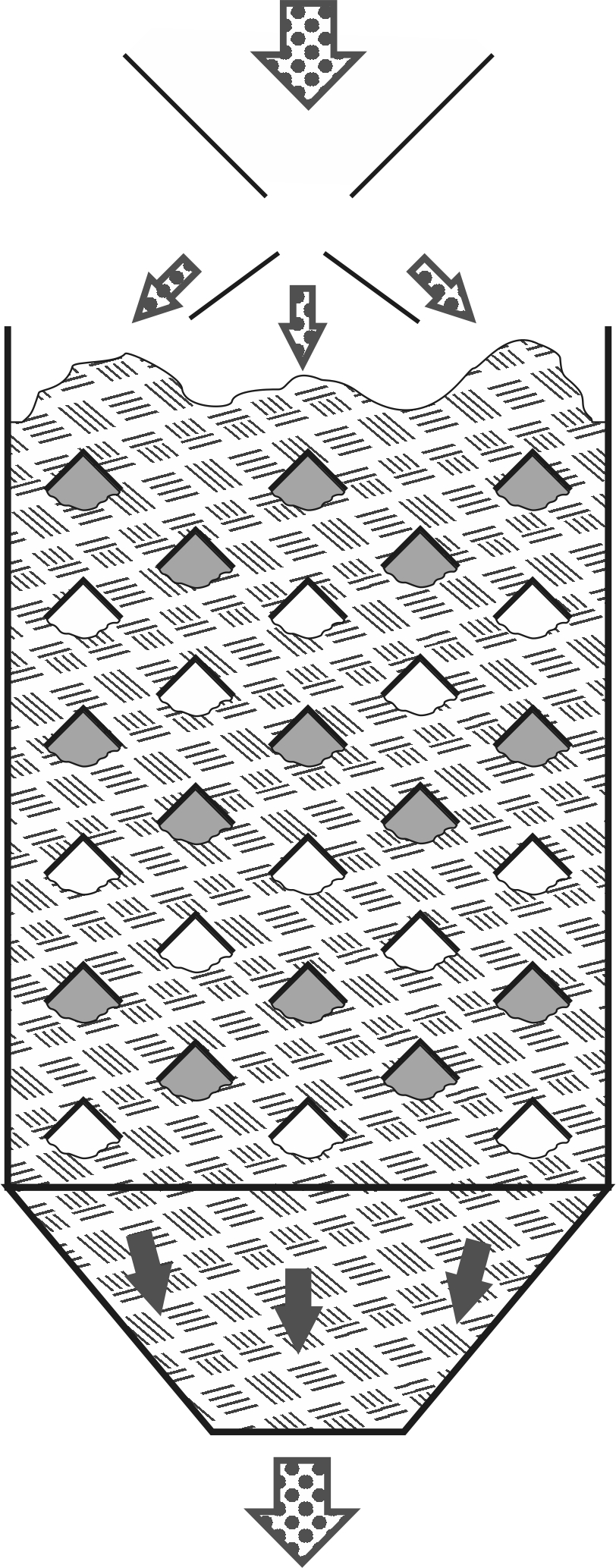
 For capacities over 20 tons per hour, a shaft-type cooler is a more compact and cost-effective option. In this design, the internal cavity is divided into numerous air ducts that penetrate the pellet mass horizontally, alternating with cavities that supply fresh air. Air passages are formed from above by metal angles 2-3 mm thick with a shelf width of 100-150 mm, directing pellets around them, and from below by the natural angle of granule repose. The cooler's body is a rectangular parallelepiped with two perforated walls. One side is for air intake, and the other for steam extraction into a unified cavity, and then, as usual, into the aspiration system.
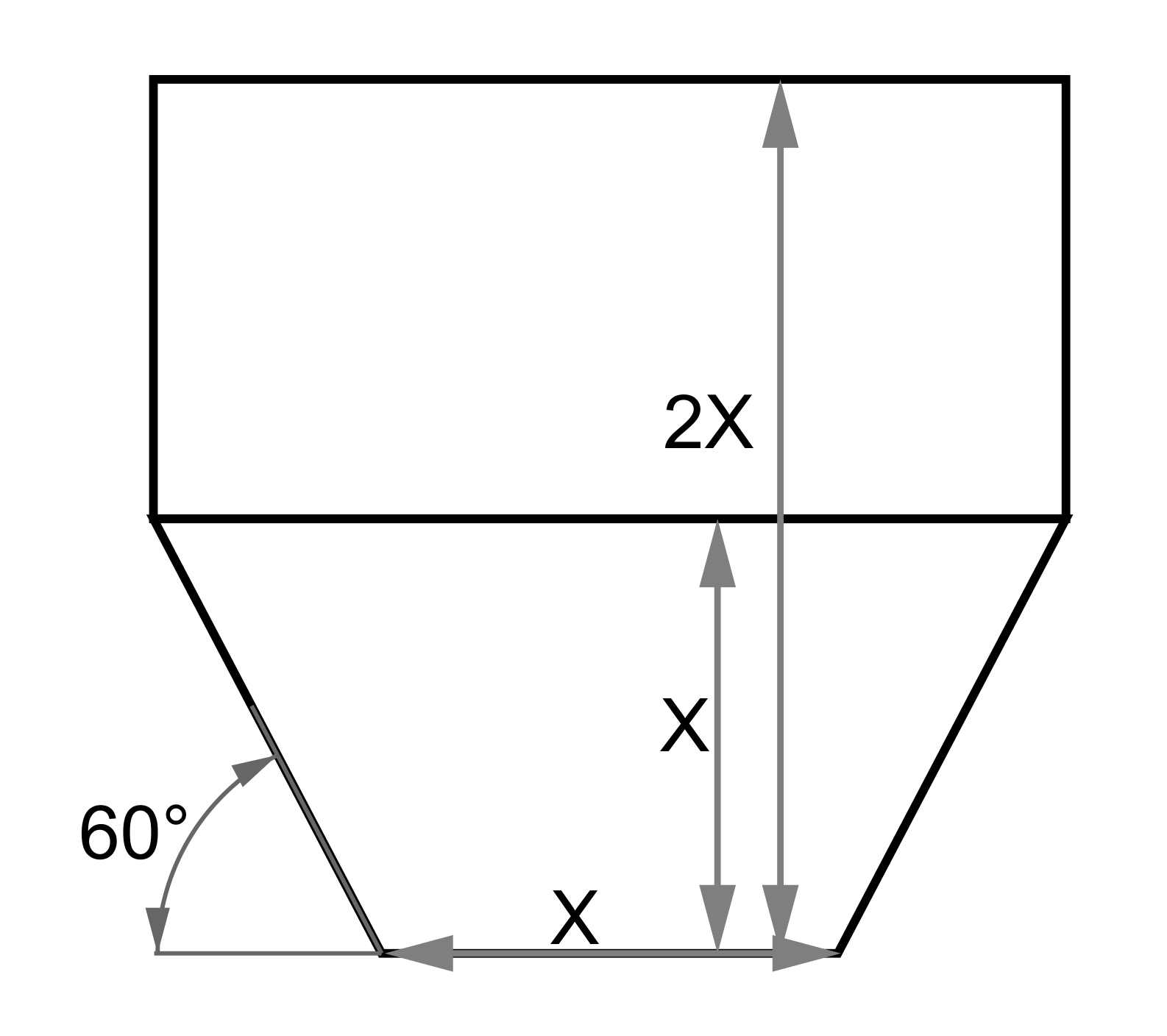
To provide rigidity to the horizontal angles, vertical posts with slotted profiles are installed, with spacing between posts being 0.5-1 meter depending on the angle thickness and rigidity. If the bend angle of the angles is reduced from 90° to 60°, and ties are welded to the shelf edges at 0.3-meter intervals, then for a cooler thickness of 2-2.5 meters, one row of support posts in the middle of the angles is sufficient.
With such a configuration and dimensions of a cooler sized 2x2x3 meters (6.6x6.6x9.8 feet), the cooling zone capacity, accounting for air duct voids, is about 5-6 tons, with a capacity of 15-20 tons per hour.
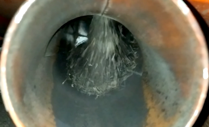
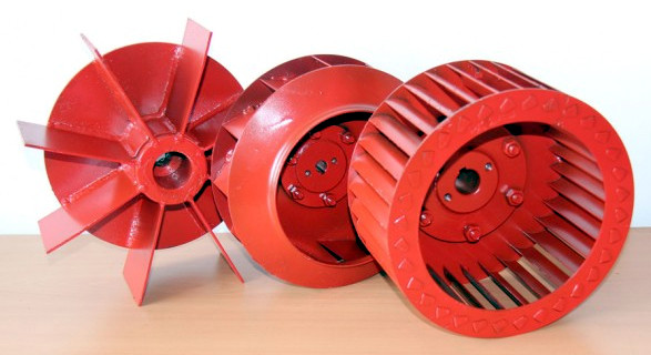
The outlet from the unified cavity to the aspiration air duct needs to be at the very bottom with a separate funnel so that particles and dust are effortlessly caught by the air stream and do not form stalactites. Otherwise, pieces of dried dust could damage the fan impeller or create a blockage in the duct. When processing mixed feed, such deposits can become damp and serve as a source of harmful microflora for animals.
The spacing between the centers of vertical rows is maintained at 150-200 mm (6-8 inches), ensuring that the average layer of pellets between incoming and outgoing air is 250-350 mm (10-14 inches), taking into account the spacing of air ducts in the cooler's internal space.