When working with raw fuel, swirling in the combustion chamber is undesirable because it can lead to an explosion or at least a loss in combustion efficiency. When using dry fine fuel, volumetric combustion is the main and most common method. At large power plants, coal is burned primarily using the pulverized coal combustion method. In this process, coal is ground into a fine powder. Wood can be burned in a similar way, but the specific costs for pulverizing are several times higher, and the calorific value is lower. Therefore, burning wood flour of the smallest fractions is economically impractical. The value of wood flour makes burning it akin to "burning money," as its micronized fractions are typically three times more expensive than pellets due to its wide range of applications.
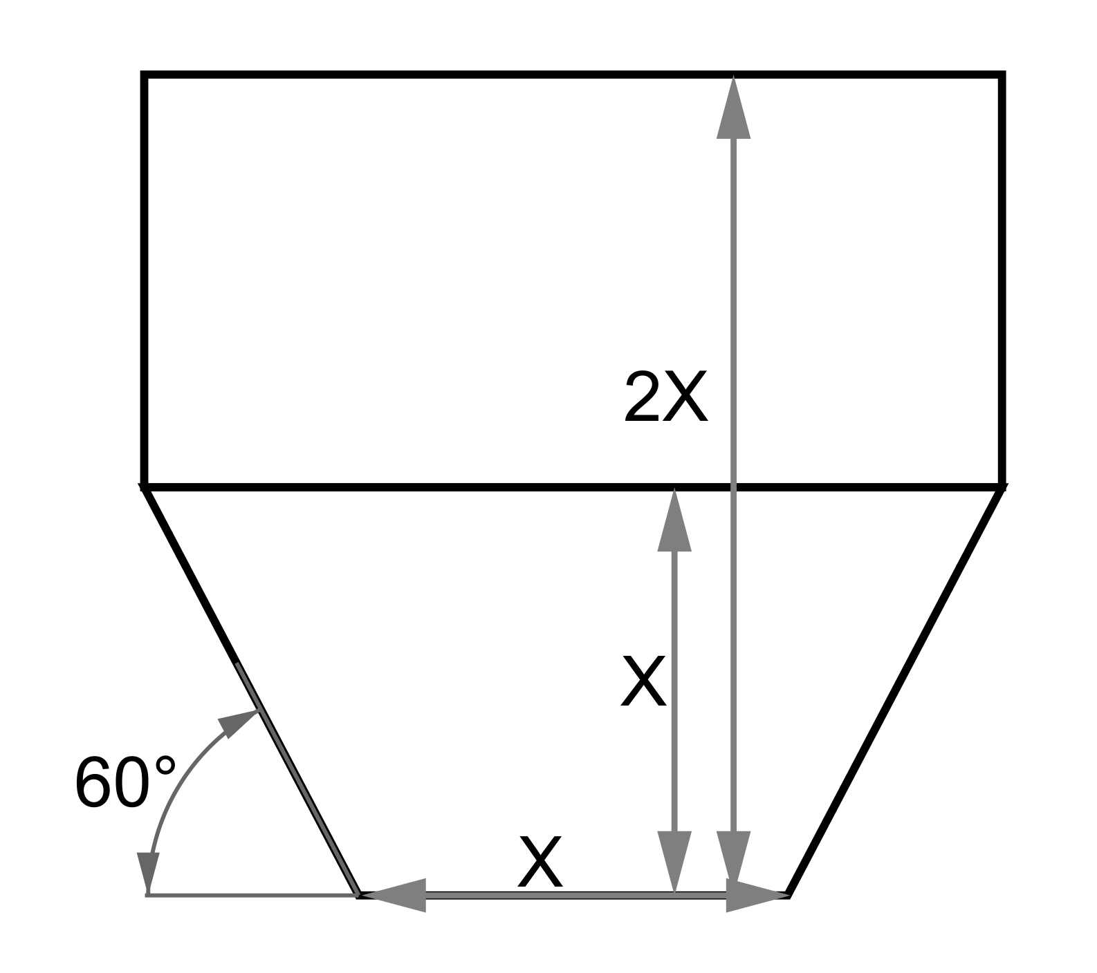
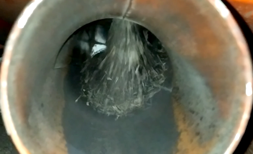
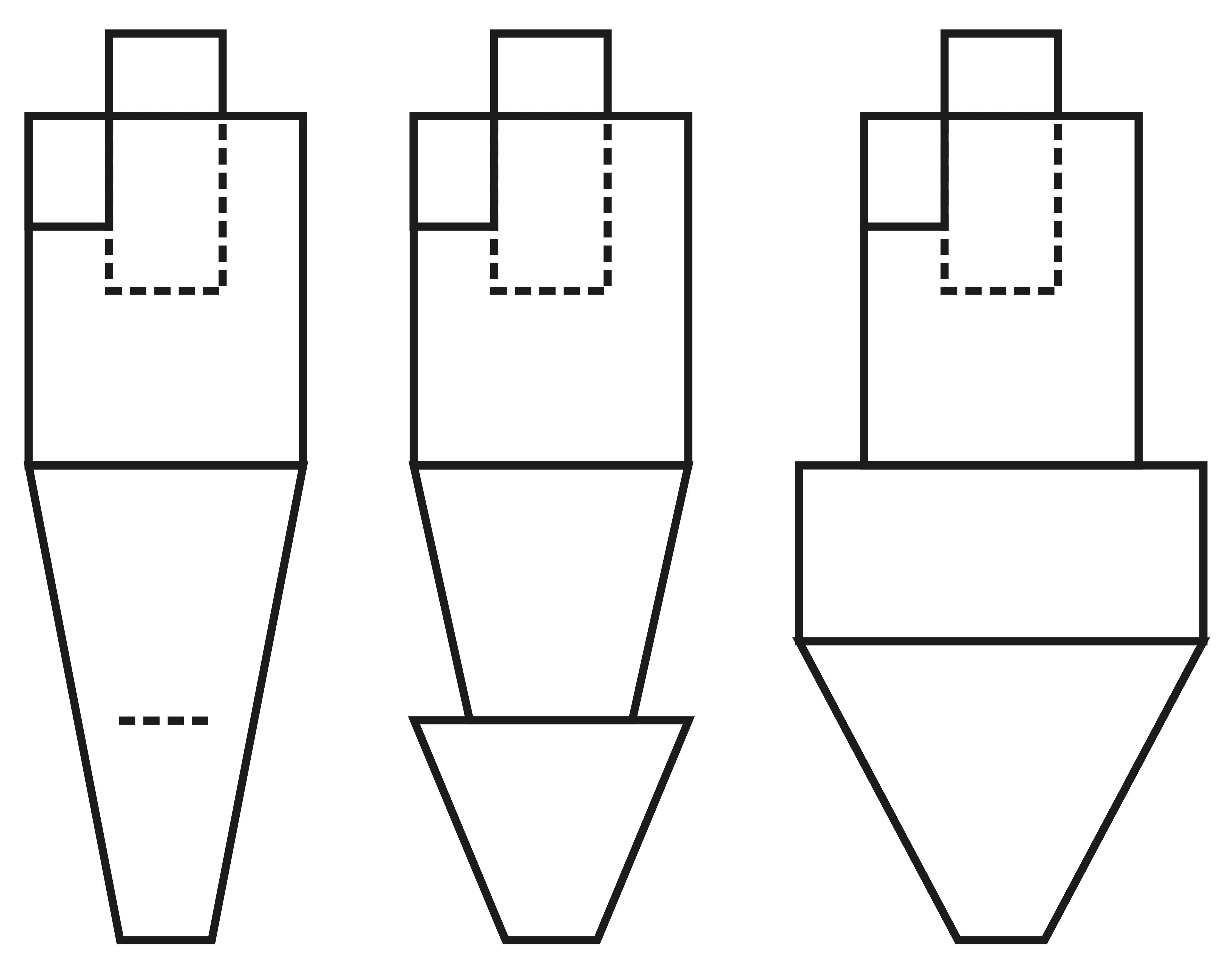
 For burning dry sawdust and fine wood shavings, round combustion chambers are used. Air is introduced tangentially at a speed of 20-30 m/s (66-98 ft/s) in small quantities so that it completes 5-7 rotations before being expelled to the upper part. During this time, the air mixes with the suspended sawdust, which burns in the flow. The rotation speed of the vortex helps in deflecting unburned embers and sparks to the surface of the refractory lining. The inlet duct is purposefully narrow to ensure that a significant part of the fan's energy is used to accelerate the jet, enhancing the rotation of air and gases within the combustion chamber. Thus, the cylindrical vertical chamber acts as a cyclone to separate larger particles and as a mixer of combustion gases with incoming fresh air from the start-up pipe. Sometimes the brickwork narrows by 1-1.5 bricks in the middle of the chamber to better retain shavings in the lower "hot" part of the heat generator. There is no actual combustion mirror here, so the power is assessed by measuring the volume of the lower part of the chamber up to the secondary air mixing window used for afterburning or diluting the combustion gases.
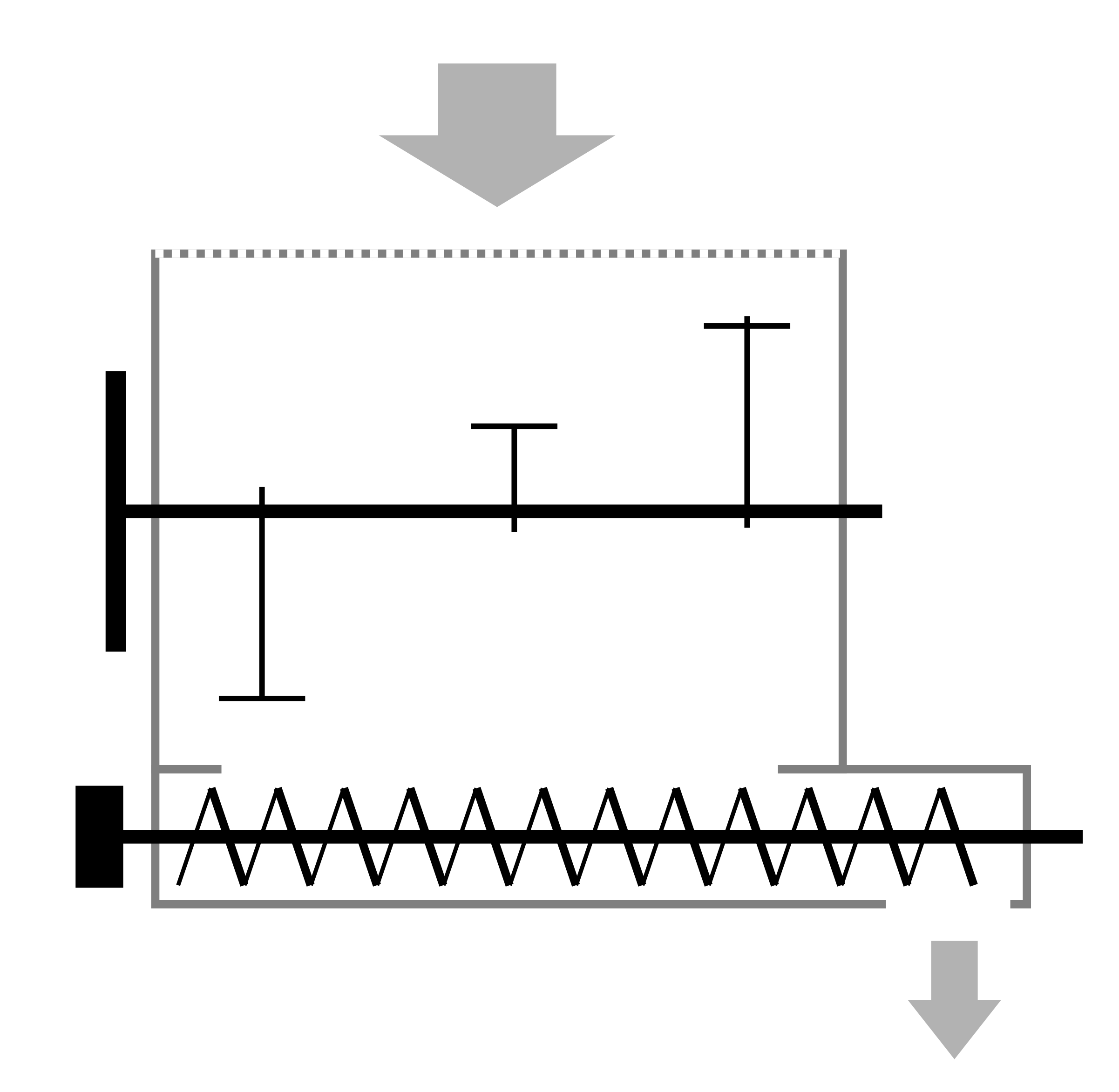
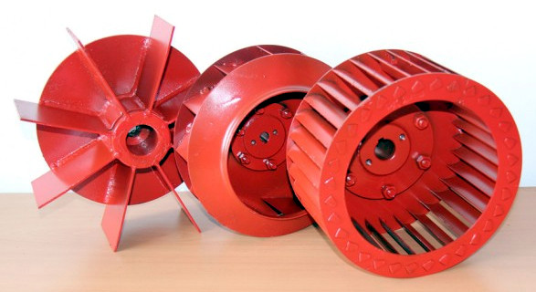
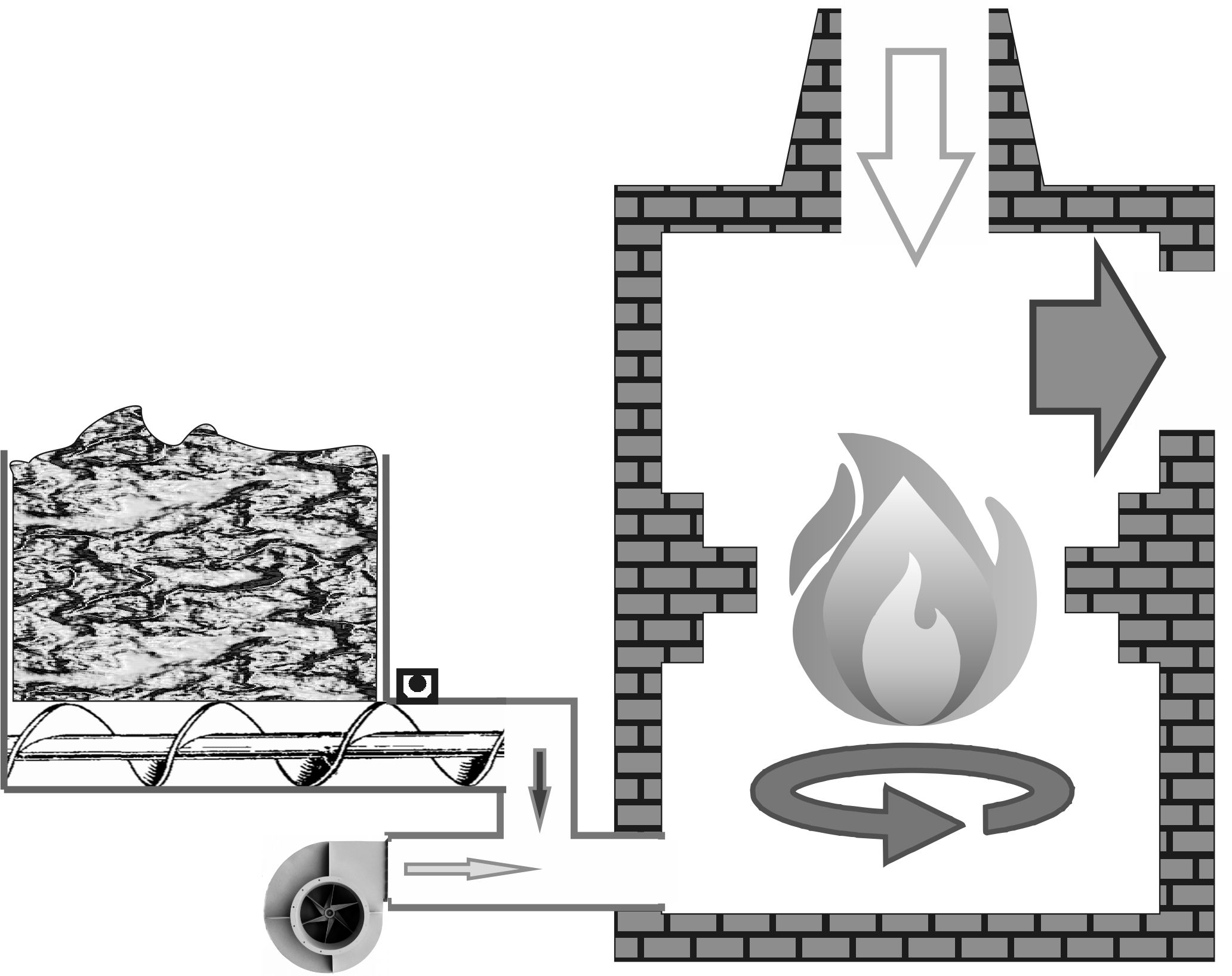
The main feature of vortex heat generators is the supply of fuel using the lowest, main fan. For fine dry sawdust, a so-called "product" fan is used, which draws sawdust from the dosing screw. The gap of 20-40 mm (0.8-1.6 inches) between the fan’s throat and the screw acts as a guaranteed break between the combustion chamber and the fuel hopper. This solution ensures safety in case of sudden power loss since the feed line contains almost no dust capable of smoldering. Fire does not travel backward through the stream of dry sawdust because the maximum possible flame propagation speed in dusty air is 22 m/s (72 ft/s) achieved only with twice the excess of fuel to stoichiometric. In this case, the work is always on a heavily lean mixture where the flame propagation speed does not exceed 3-5 m/s (10-16 ft/s). For shavings, a screw feed into the duct between the fan and the combustion chamber is often used to reduce the wear on the impeller, which also ensures fire safety during sudden power outages. However, such a duct must have a sufficient bend so that thermal radiation from the refractory lining does not reach the remnants of shavings at the end of the screw. In any case, it takes 10-30 seconds to fully stop the fan impeller, during which time the feed line is adequately purged. With normal heat generator operation, the airborne sawdust burns in 5-10 seconds, so upon inspecting the combustion chamber one minute after an emergency stop, no traces of fuel are found. For a restart, it is necessary to load wood and wait for stable burning. The minimum fuel amount in the hot zone with rapid combustion is the safest option for burning wood in the context of pellet production.
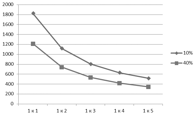 The calculation and adjustment of such a heat generator contradict the common belief that "the more you blow, the higher the temperature." We are dealing with stoichiometry, the relationship between the mass of fuel and air for complete combustion. Surprisingly, increasing the fan speed into the furnace actually lowers the temperature by diluting the combustion gases with excess air. If the air is supplied just right for burning the fuel, the vortex temperature can reach 1800°C (3272°F). Doubling the air supply results in around 1100°C (2012°F), which is the upper limit for operating refractory materials. Therefore, it is best to maintain the temperature between 700 and 850°C (1292 to 1562°F) to safely burn off all carbon without causing accelerated wear. It has been found through experience that if the furnace temperature falls below 500°C (932°F), combustion becomes unstable, and there is a high risk of transitioning to a smoldering mode with dangerous gas buildup. Hence, the automation sets the lower limit at 600-650°C (1112-1202°F), corresponding to a fourfold excess of air. Only dry fuel allows for such a wide range of ratios, and with sawdust moisture content of 30-40%, self-ignition during flight requires a lot more energy and stable combustion is difficult to achieve.
Coincidentally, moisture content around 10% is close to ideal for pelletizing, and just before being fed into the pellet mill, the material already has a size of 2-3 mm (0.08-0.12 inches), ensuring quick and efficient combustion in the flow. Therefore, similar to heat generators using pellets, fuel for the vortex heat generator is taken in a dried state from the production line but before pelletizing. This reduces the specific electricity costs for pressing the fuel for internal needs, retaining the benefits of using pellet burners while simplifying heat generator management and overall maintenance.
The control logic for a vortex heat generator is based on the principle that at a constant output flow of the gas mixture, its temperature depends solely on the amount of fuel supplied. The automation maintains the temperature of the drying agent in a narrow range by adjusting the frequency of the screw feeder drive that feeds the sawdust. To maintain optimal combustion temperature in the furnace, the fan speed is automatically adjusted to determine which part is fed through it and which through the ignition tube. This type of control does not necessarily require a controller, but just temperature relay signals directly to frequency converters controlling the drives. When the preset temperatures are reached, the respective drives slow down or speed up, keeping temperatures within a narrow range. In pilot lines, simple automation has managed to limit the amplitude of temperature fluctuations at the dryer inlet to within 10-15°C (18-27°F).