Wood stoves are intentionally placed at the end of the list because even their largest versions in standard execution are not very suitable for use in pellet production. Automating the supply of firewood is nearly impossible, as all pieces of logs vary in diameter, requiring adjustment based only on the degree of burning and exit temperature. Loading logs causes temperature spikes: initially, the temperature drops sharply during initial heating, then the pyrolysis gas ignites, and the temperature rises sharply. As the wood chars, the temperature slowly decreases. It is crucial to add logs to the coals in time; otherwise, you will need to ignite the fire again. While the operator can be attentive and creative in the hours early on, by the end of the shift, excessive loading often occurs, cooling the furnace. After ignition, the surplus wood creates soot due to a lack of oxygen. Soot in the drying agent leads to significant darkening of the pellets, and temperature fluctuations reduce pellet quality because its moisture content ranges from 5 to 12%, exceeding allowable limits, including strength and bulk density parameters.
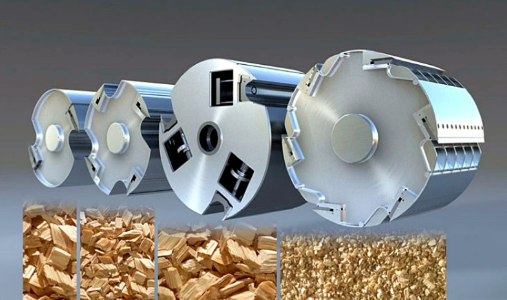
Nevertheless, there are many places with an abundance of wood resources and raw materials for pellets, such as fresh sawdust, which should not be burned as they produce bright, attractive pellets. Converting balance wood into chips would add a wood chipper to the production line and involve installing a rather expensive heat generator. The goal is to profit from processing sawdust into pellets using non-liquid wood with minimal equipment costs. There are two options here.
Trained Operator
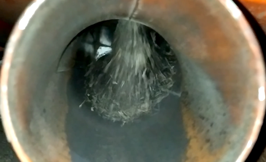
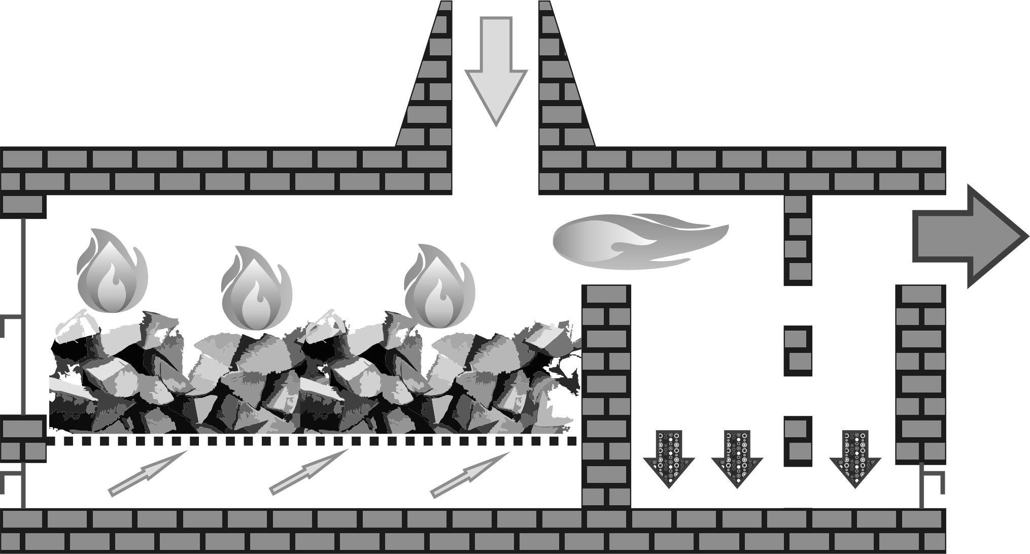 The stove is built traditionally with a rectangular combustion chamber lined with grates. It is recommended to protect the far wall of the combustion chamber with a thick steel sheet, installed with a piece of rail across the chamber or with another improvised deflector, to prevent incoming logs from destabilizing the bricks. At the end of the chamber is an ignition pipe leading to a cavity for afterburning, mixing, and spark quenching. The purpose of this chamber changes depending on operating conditions and circumstances. It is usually divided into two parts with a wall of firebrick, built with gaps. Since the air from under the grates passes through a significant layer of wood, most of the time, there is not enough oxygen for complete soot combustion, and the air drawn from the ignition pipe extends the flame tongues into this supplementary chamber. The mixing chamber volume should be no less than the combustion chamber volume above the grates. At the base, doors should be installed for ash removal. The operator loads the logs alternately on the left and right sides of the grates as the wood chars. While the wood ignites on one side, the coals maintain high temperatures on the other. The operator estimates the volume of wood in each load by peering through the door crack: the mix chamber exit should be clearly visible when the wood is burning without smoke and soot interference. If the logs are packed too tightly, the operator can partially close the air intake, reducing burning intensity within the mass of wood. Pyrolysis gases will then burn in the mixing chamber.
Although this is the most unstable way to provide heat for the dryer, it uses relatively little wood and is often practiced on production lines with a capacity of 500-800 kg/h (1102-1764 pounds/hour). If there is a lot of wood and it is conditionally free, it is possible to install 10-20 steel pipes with diameters of 100-150 mm (4-6 inches) in the chamber behind the furnace, creating a primitive heat exchanger. This will increase fuel consumption approximately twofold but will eliminate soot mixing with the drying agent, and most importantly, eliminate the risk of accumulating flammable gases inside the dryer.
Semi-Automatic Operator
The second option is automation for boost and afterburning fans. This is an enhanced version of the first option where the automation monitors temperature and afterburning, but you’ll still need to keep an eye on feeding wood. Comparing this to a vortex heat generator, the boost fan acts as an accelerator of pyrolysis gas release, similar to supplying gaseous or granular fuel. It regulates the power of the heat generator and maintains the stability of the thermal agent’s temperature entering the dryer. If too much wood is loaded, the boost fan will automatically reduce the intensity of combustion temporarily, based on the increased temperature at the dryer’s inlet. If this fan speeds up beyond set limits, it means there is not enough fuel, and it’s time to add more. Some frequency converters have a dry contact that closes at the maximum preset, which can be used as a signal for adding wood by lighting up a bulb for the stoker.
The afterburning fan supplies air to the lower part of the ignition tube or the sidewall of the combustion chamber horizontally, helping to burn the pyrolysis gases completely. A thermal relay installed at the outlet from the combustion chamber helps the afterburning fan maintain such performance that the temperature of the gases supplied to the mixing chamber does not exceed 900°C (1652°F). This fan operates on an inverse relationship: the higher the temperature in the afterburning chamber, the faster the impeller turns to dilute with fresh air, ensuring the airflow does not provoke wood ignition. It’s important to mention that having operational fans with a sealed ignition tube necessitates equipping the heat generator with a vacuum sensor. This sensor acts as an emergency feature, triggering a respective mode in the absence of vacuum in the combustion chamber. Otherwise, pyrolysis gases could escape into the facility, posing a poisoning hazard to the staff, and flames escaping from cracks would be quite memorable. An alternative is to use throttling dampers with servos instead of fans with frequency converters, but this requires a small controller. No matter the method for metering the supplied air, it is crucial to have turns in the ducts or protective screens to prevent overheating of the impeller and servos, avoiding distortion and breakdown.
Emergency Shutdown
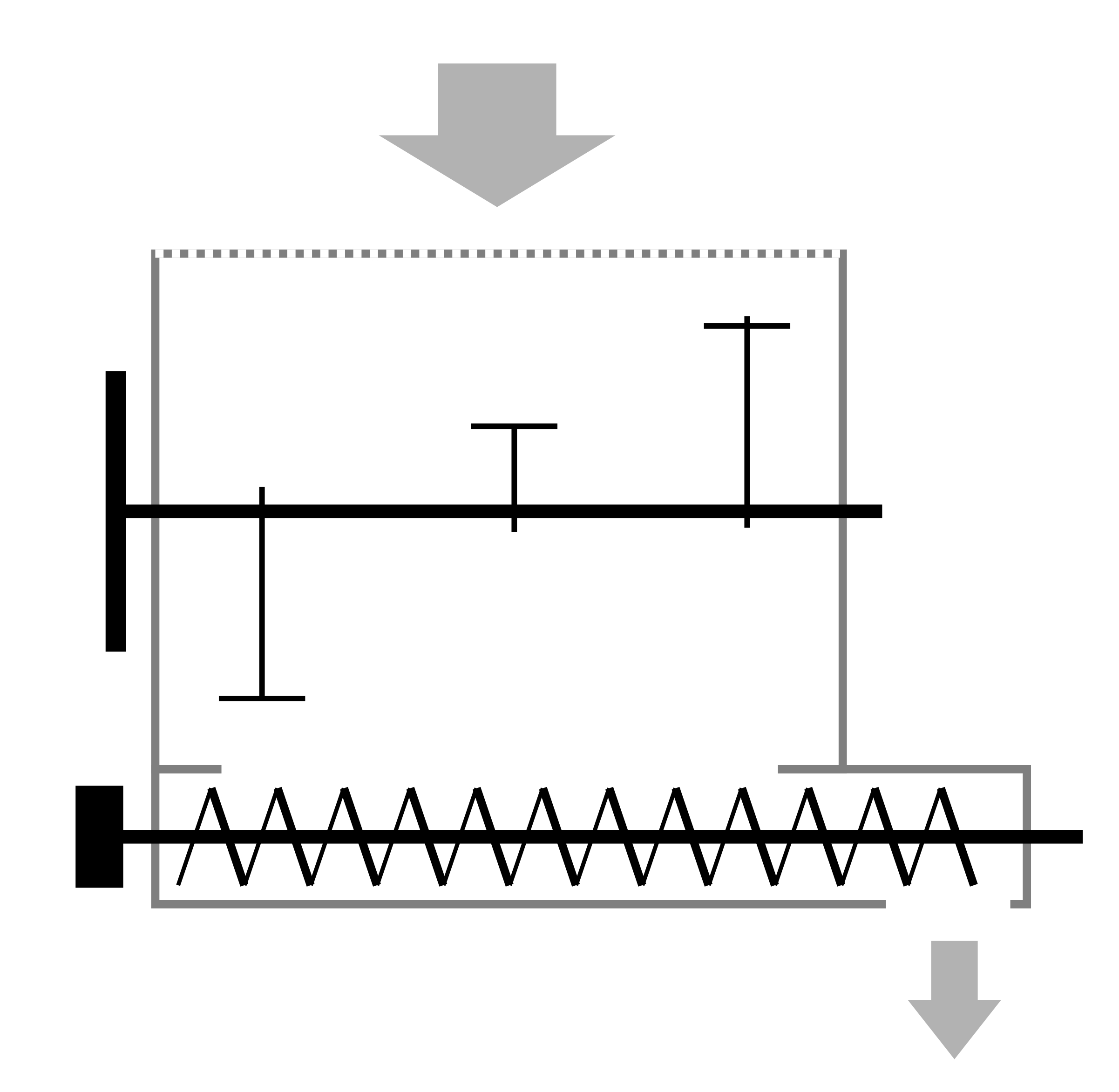
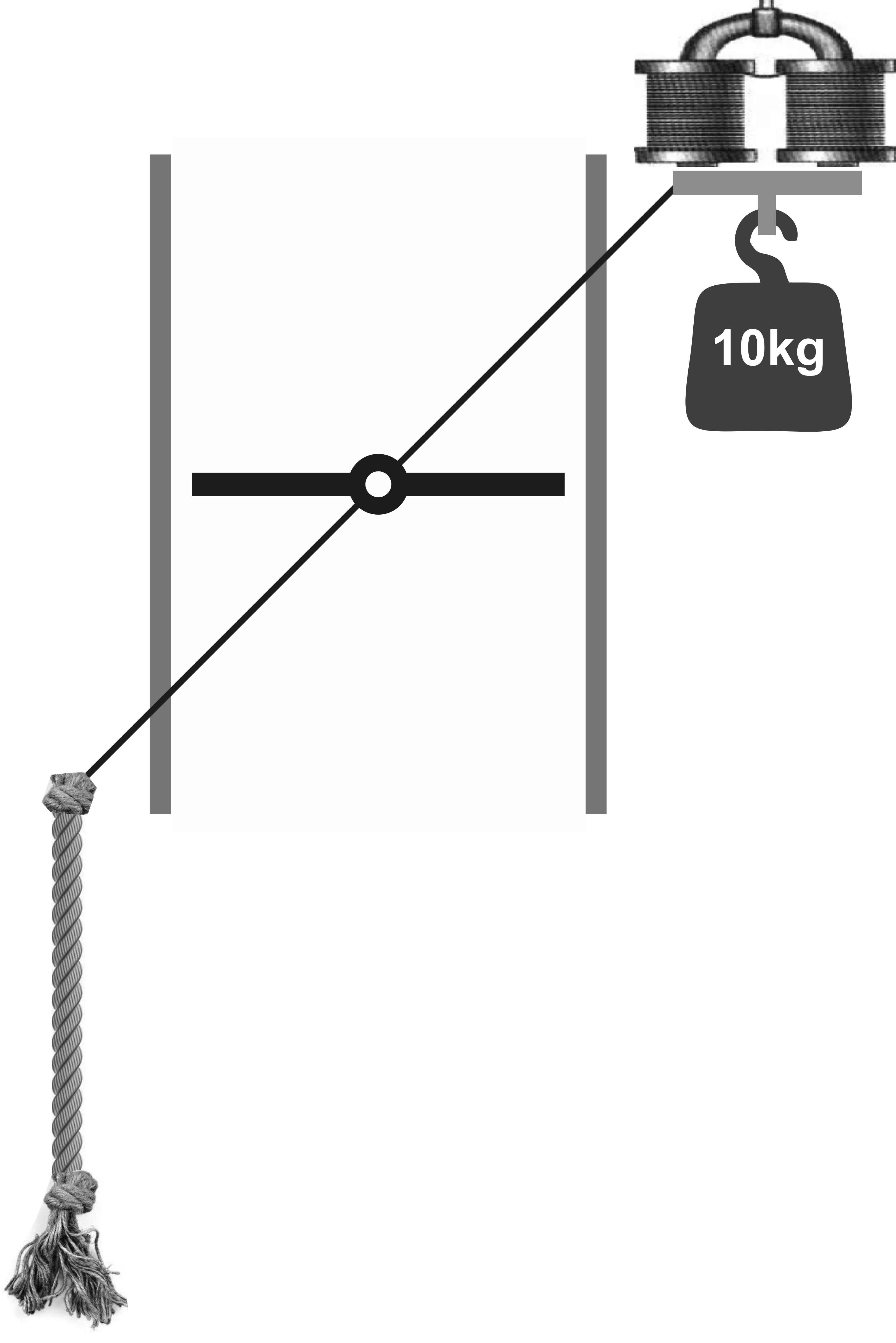 The emergency mode usually involves disconnecting all drives, fans, nearby operating equipment, and opening the ignition tube damper. The simplest automation for an emergency damper is a lever-based opening with a pre-attached weight. On the other end of the lever, a steel plate is welded which is held by a door electromagnet. That is, when the power is on and there is no emergency, the electromagnet is engaged. To switch from ignition to operational mode, the stoker pulls a rope and closes the damper, bringing the plate to the electromagnet. In the event of a sudden shutdown or emergency, the ignition tube opens and creates sufficient draft so that air is drawn inside through all technological openings and gaps, carrying away all burnt and unburnt materials out of the facility.
For wood-fired heat generators, it is essential to have a damper that can cut off the connection to the dryer. If for some reason the firewood is overfilled, they ignite, and cannot be stopped, a shortage of air will quickly turn the process into pyrolysis, filling the dryer with explosive gases. Alternatively, the temperature may uncontrollably rise, leading to a fire if there is not enough material to dry or if it is too dry. Using a damper to cut off the system is the only and most effective method for emergency shutdown. It is understood that the start-up pipe in any heat generator burning wood and similar pyrolyzing fuels must not only exist but also be of appropriate diameter and height. It is recommended to have at least 8 cm² of pipe passage area for each thermal 1 kW of power. For a 1 MW heat generator, the start-up pipe diameter should be no less than 500 mm (20 inches), and for 500 kW, no less than 350 mm (14 inches), with a pipe height of at least 6 meters (20 feet). Such conditions necessitate mounting the start-up pipe on a special frame to relieve the load from the brick heat generator, sealing the joints with special insulation and mortar.