When the quality of the die is sufficiently high, determined by the glossiness of the die surfaces, it is usually possible to predictably select the necessary hole length for stable operation and good pellet quality. It is much simpler to indicate the ratio of the diameter to the length of the holes, which helps determine parameters for any pellet diameter with the same raw material. The stickier and softer the raw material, the shorter the hole length needed to achieve maximum output. Animal feeds require a significantly longer hole length, although they bind quite well, but need to heat up within the die at high feed rates rather than on the track surface. Differences may occur in the required pellet density depending on the application. The table provides data based on practical operation of pellet mills with the inner die diameter of 480 mm (18.9 inches), although these ratios do not differ significantly with other diameters and are more driven by the pellet mill's design rather than raw material properties:
| Hole Diameter, mm (inches) | Compression Ratio | ||||||||
| Wide Track (120 mm or 4.7 inches) | Narrow Track (78 mm or 3 inches) | ||||||||
| Feed (80% grain) | Green Mass, Cake, Sunflower Husk | Manure | Asphalt Additives with Bitumen | Sawdust | |||||
| Poultry | Pigs | Fish | Pine, Aspen, Birch | Birch (Steam) | Hardwoods | ||||
| 2.5 (0.1) | 1:11 | 1:8.5 | 1:12 | / | / | / | / | / | / |
| 3 (0.12) | 1:10.5 | 1:8.5 | 1:11.5 | / | / | / | / | / | / |
| 3.5 (0.14) | 1:10 | 1:8 | 1:11.5 | 1:10.5 | 1:4 | / | / | / | / |
| 5 (0.2) | / | 1:7.5 | / | 1:10.5 | 1:4 | / | 1:6.5 | 1:8.5 | 1:5.5 |
| 6 (0.24) | / | 1:7.5 | / | 1:11 | 1:4 | 1:6.5 or 1:3.2 | 1:6.5 | 1:8.5 | 1:5.5 |
| 8 (0.31) | / | / | / | 1:12 or 1:14 | 1:4 | 1:6.5 | 1:8.5 | 1:5.5 | |
The ratios indicated are applicable to most pellet mills with a ring die, and noticeable deviations typically indicate a breach in technology or suboptimal operating conditions of the pellet mill. It is essential to remember that the particle size of the raw material should not exceed half the diameter of the die hole. Otherwise, the formation of the mass is disrupted due to uneven heating and compaction, leading to a sudden increase in load and unstable pellet quality. If, for some reason, very fine particles must be processed, a longer channel length is required. For example, birch sawdust, with the addition of about 1% starch, binds well on a coniferous die with a ratio of 1:6.5. However, birch sanding dust requires a ratio of 1:7.5 or more and responds weakly to starch additives.
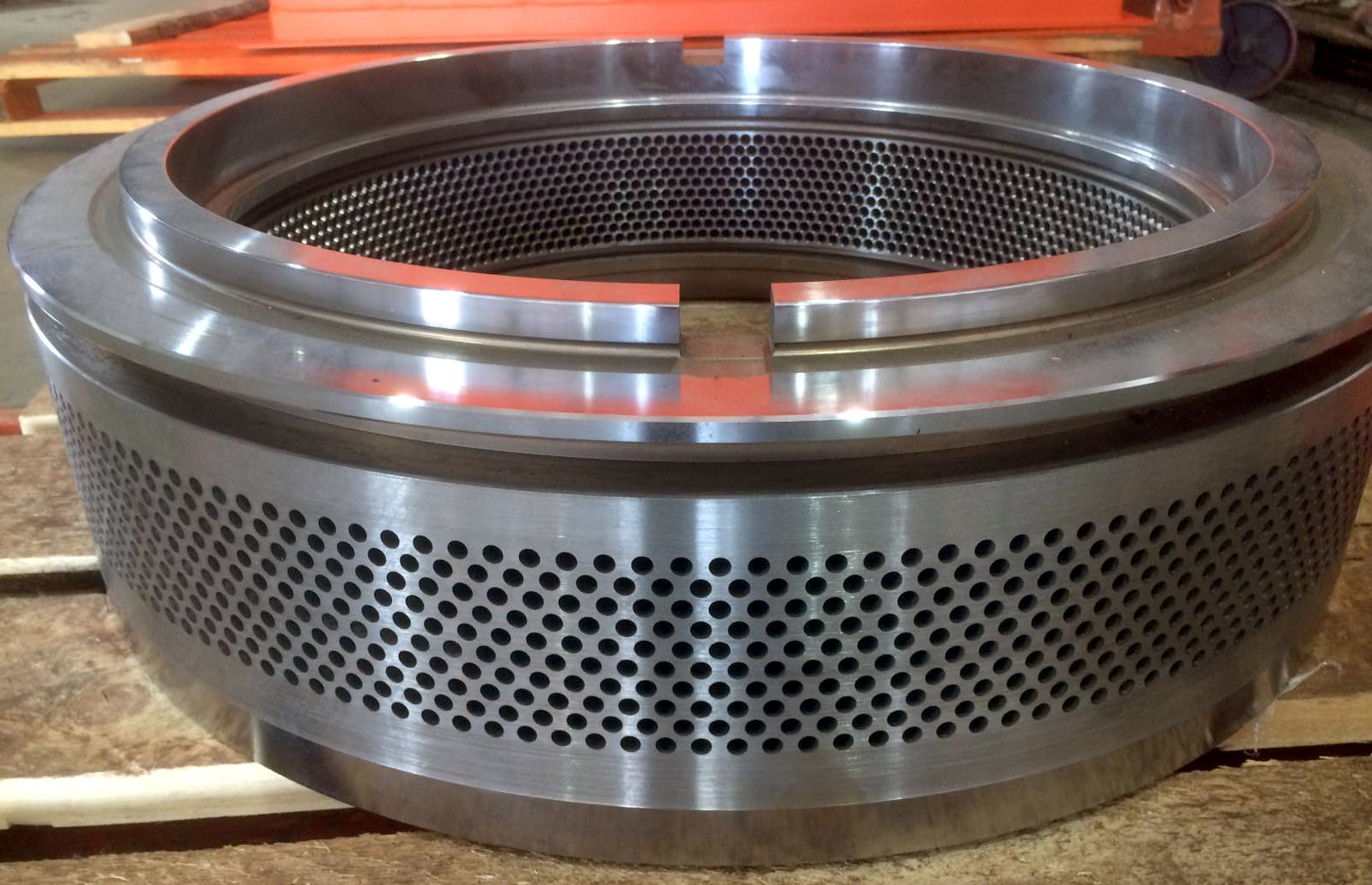
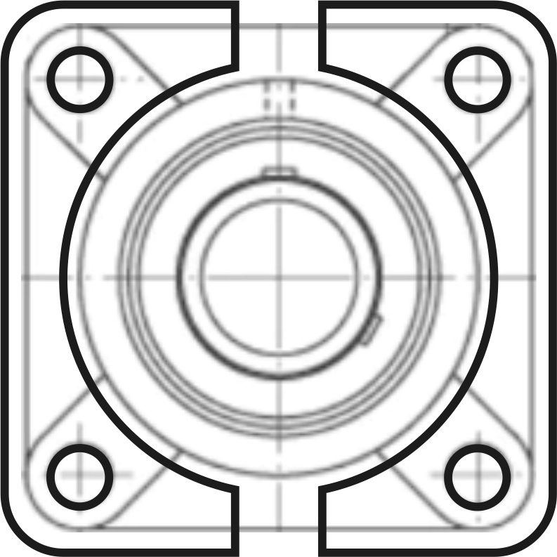
 The working length of the holes is not the thickness of the die. The reason is that, regardless of the diameter of the die holes and the width of the track, there is a limiting mechanical load that a specific ring die can withstand in a particular pellet mill. By reducing the diameter of the die holes, it is necessary to shorten them to maintain the die's strength and prevent cracking or total destruction. To achieve this, counter-drilling with an 8-15% larger diameter drill bit is applied. This way, the material is released sooner than it exits the die. Naturally, there's a temptation to use a thinner die for relatively light material, saving on forging costs. Such cases are exceptions to the rule and are applied in small models for home use or for pelleting very soft and sticky materials with minimal load on the pellet mill, where the current load on the main drive is similar to idle. The picture shows an example of a die design for processing chicken manure. In many fertilizer productions, the die thickness is reduced from 85 mm (3.3 inches) to 50 mm (2 inches) because the manure is fairly sticky, and with a relatively short working length of the hole, the load falls to 50-60% of the nominal without reducing productivity and pellet quality.
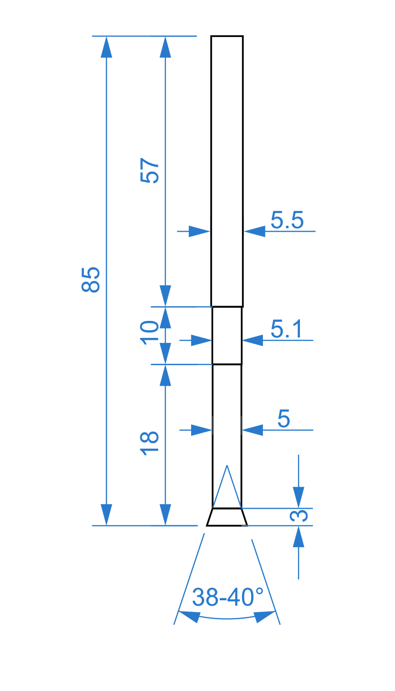
 Earlier, a countersink at the entrance to the die hole was mentioned, which aids in the compaction of the raw material, facilitates the cutting of the heated layer, and guides the particles into the die holes. The depth and angle of the countersink are often determined as standard for each type of material. In practice, this angle is easiest to determine on a die that is approximately halfway through its service life, with the countersink being worn down naturally by the material. Essentially, the initial conical recess simply eases the start-up of the equipment and ensures smooth operation during roll-in and wear-in with the roller surfaces. For most types of material, the angle of the countersink measured closest to natural is 38-40°. This can be checked visually by aligning a spade bit with the hole. When there is a shortage of material due to an overly low feed rate for the width of a given die track, contact occurs between the rollers and the die. As a result, the countersink flattens, and the funnel at the die hole entrance disappears, leading to unstable operation and increased load on the rollers, while producing loose pellets.
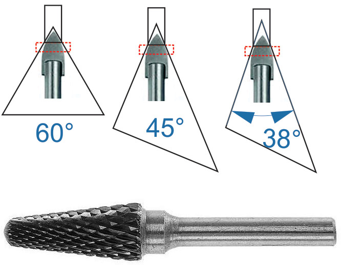 Restoring the countersink is quite simple with a conical carbide rotary burr installed in a powerful enough cordless screwdriver or drill. The largest diameter of the rotary burr, also known as a conical burr, should be 3 to 4 mm (0.12 to 0.16 inches) larger than the diameter of the die hole to ensure a sufficiently deep countersink. With proper equipment settings and adequate material feed, optimal moisture, and particle size, such operations should not be necessary throughout the die's service life. It's important to note that attempting to bring the countersinks of adjacent holes into contact with the popular 24° cone angle of the rotary burr results in nearly twice the depth of countersink, significantly increasing resistance to extrusion.
Spade bits designed for ceramics are quite convenient for restoring countersinks. They allow for an angle range of 35 to 45°, and their cost of 2 to 3 dollars, combined with sharp edges and good wear resistance, makes them an excellent choice. For instance, creating countersinks in 2800 die holes with a diameter of 650 mm (26 inches) and a die hole of 6 mm (0.24 inches) required only 14 spade bits of 10 mm (0.39 inches) diameter. Drilling should be done with a reliable cordless screwdriver or drill at low speeds, using oil or a sufficiently lubricating coolant. Two-flute spade bits should not be attempted because they tend to break immediately due to binding.
As the die wears, its internal diameter increases. Despite the natural formation of a countersink, the working length of the die hole shortens as the die body becomes thinner. The shorter the working length of the channel, the more the wear affects pellet quality. The main method of addressing this is step-drilling. The second part of the die hole has a diameter 0.05 to 0.1 mm (0.002 to 0.004 inches) larger, with this section being only 5 to 10 mm (0.2 to 0.4 inches) long. Once the die hole wears to this diameter, the second section comes into play, extending the working length by these 5 to 10 mm (0.2 to 0.4 inches) and maintaining the compression ratio and pellet density. This can increase the lifespan by 50 to 70% for a die with a 6 mm (0.24 inches) hole, designed for processing softwood.
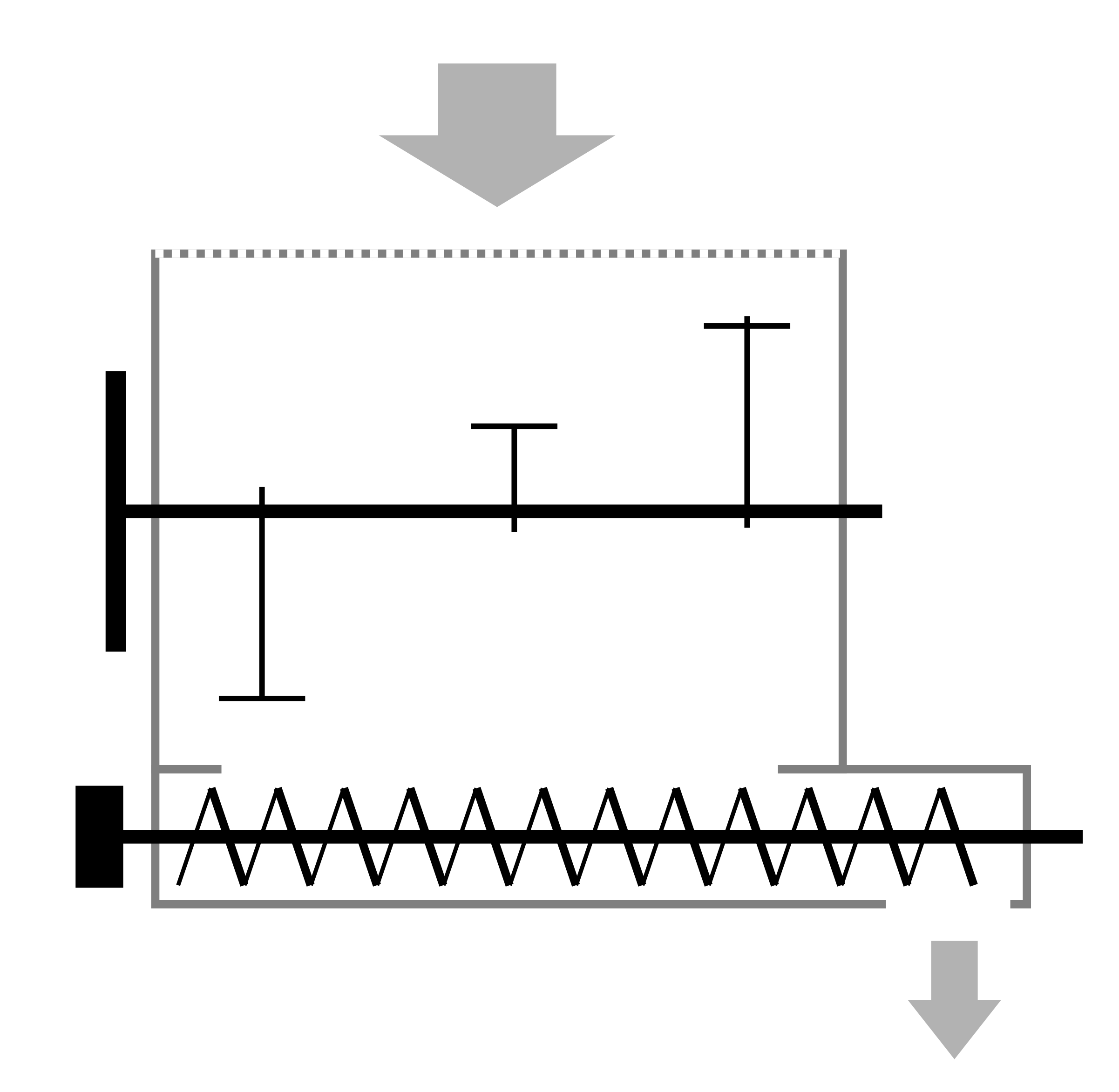
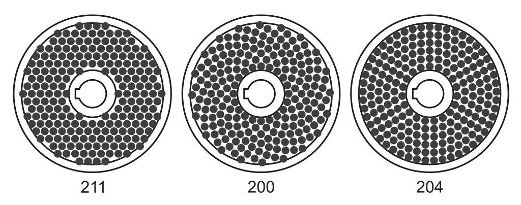
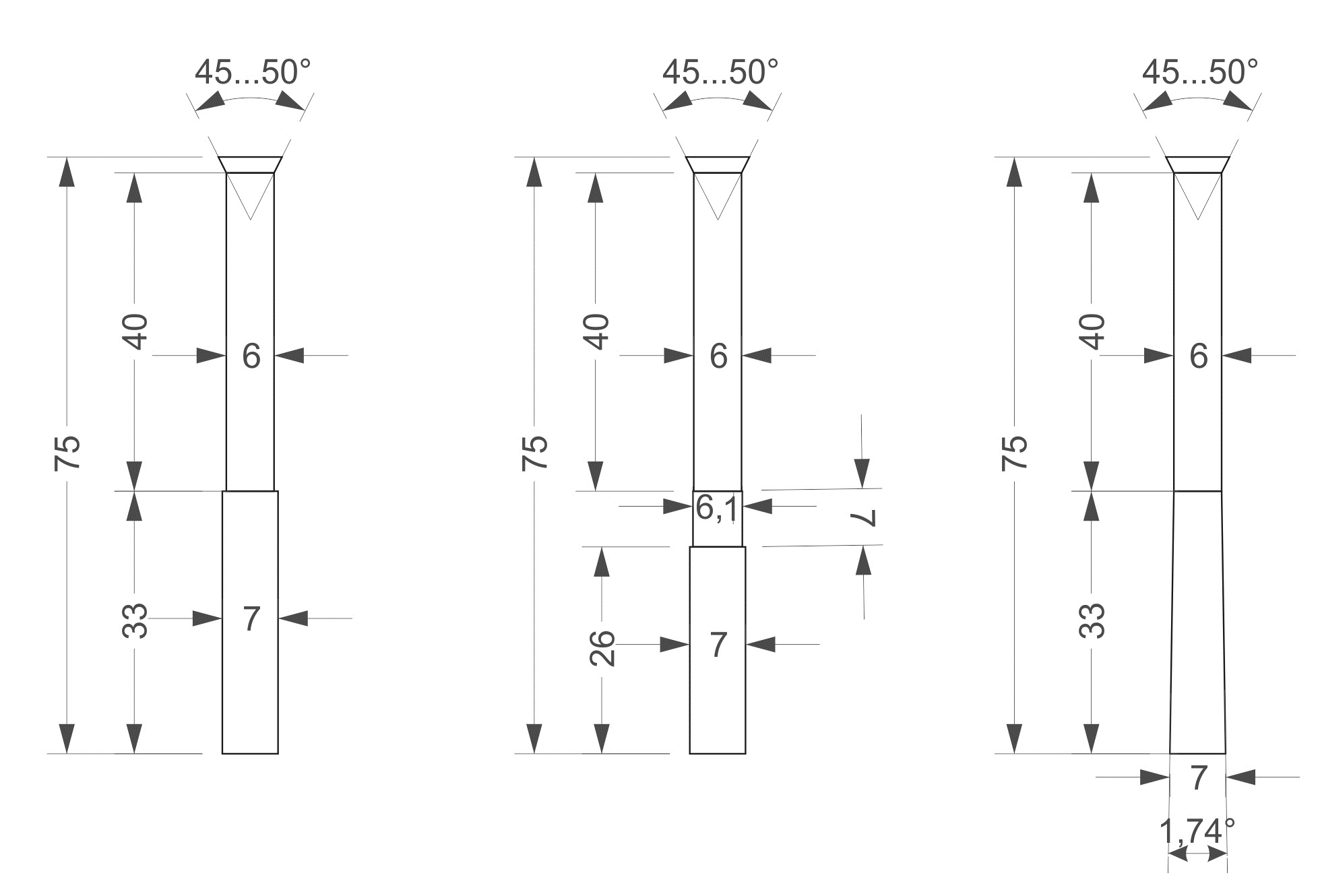 For dies with very small hole diameters, making a counter-drill with a large diameter difference becomes problematic, especially with a short channel length. The increased diameter due to closely spaced die holes leaves little steel body, leading to local stresses and internal cracks, even breaking off pieces of the die. In such cases, conical counter-drilling is used. As wear occurs on the internal surface of the die hole, increasing the diameter, the encounter with the expanding part becomes further away over time. The image shows examples of regular, step, and conical counter-drilling.
Interestingly, the price of a die with step or conical drilling is not much different from the standard version. Therefore, advanced planning of stock inventory justifies the order of these specialized designs.
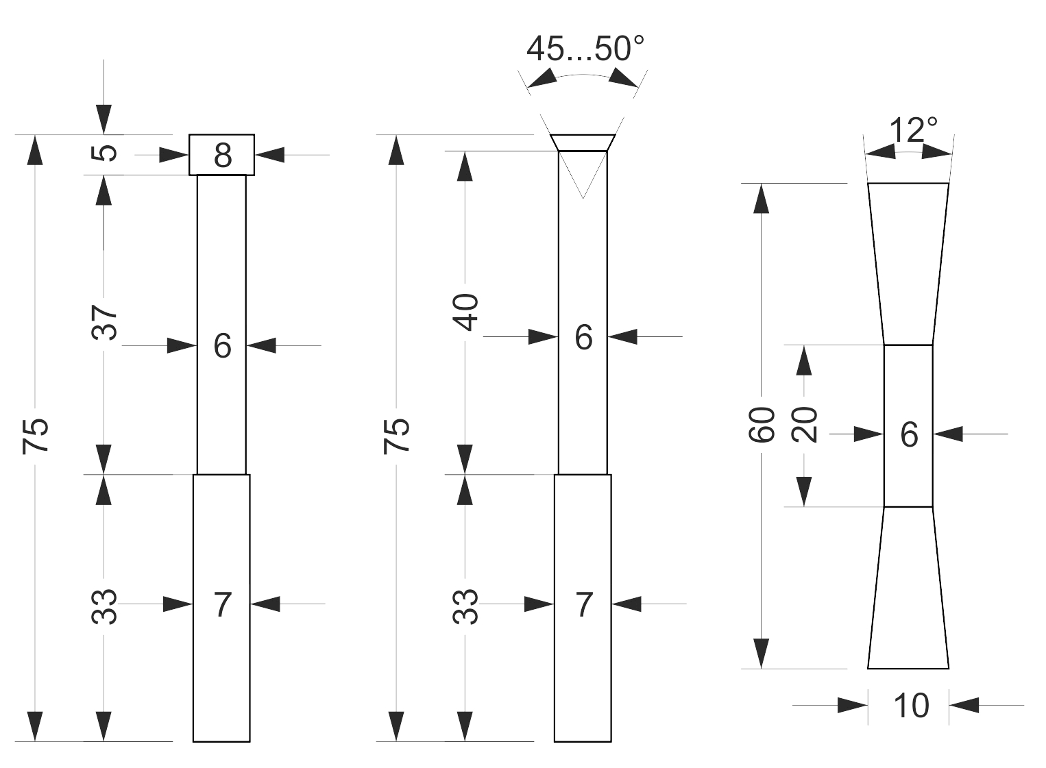 Sometimes instead of a conical countersink at the entrance to the die, a counterbore or simply a deep drilling of 5-10 mm (0.2-0.4 inches) with a diameter 2-3 mm (0.08-0.12 inches) larger than the main one is used. This, like countersinking, helps to "cut" the heated layer of material, sharply reducing the area of dead zones on the die track. The material packs into the step, forming a funnel-like shape and operates on the same principle. This solution is much more resistant to the lack of material in certain rows and also allows the geometry of the working part of the die to be maintained as wear occurs. In addition, the resistance with such an entrance is noticeably higher and the working length of the channel can be shortened. There is a suggestion that the experience with counterboring happened accidentally due to a misunderstanding of a drawing, where the dimension lines were mistaken for the shape of the entrance to the die. Interestingly, counterboring is the only way to produce a ring die for feed with a large die diameter without increasing the overall body thickness compared to standard size. For example, for pressing oilcake, an 8 mm (0.3 inches) die is used without counter drilling with a thickness of 85 mm (3.3 inches), which is already 10 mm (0.4 inches) thicker than mass-produced wood dies and strong enough. Further increases in outer diameter sharply increase the cost of forgings and machining. Therefore, for a die diameter of 10 or 12 mm (0.4 or 0.5 inches), a counterbore of 10-15 mm (0.4-0.6 inches) is used, leaving the thickness at 85 mm (3.3 inches).
On low-capacity pellet mills, very deep countersinks with a short working channel are sometimes used, mainly for feed options where loads are small and savings on die thickness are significant. In the case of flat die pellet mills, this solution allows for double-sided use of dies, doubling their lifespan.
The angle of the countersink depends not only on the hardness and stickiness of the raw material but also on the design of the pellet mill. If the compaction of the material mainly occurs on the track surface and then the finished mass is pushed into the die, an angle of 38-50° and a countersink depth of 2-3 mm (0.08-0.12 inches) is typical for most large industrial pellet mills with a ring die. If the rollers and bearings are weak, and the distance between holes is quite large to maintain the strength of the flat die, significant impact loads on the rollers can be alleviated by deep countersink compaction. In such cases, a countersink angle of 11-16° with a depth of 10-15 mm (0.4-0.6 inches) is used for die diameters of 6 and 8 mm (0.2 and 0.3 inches) with relatively thin dies. For other die diameters, similar ratios should be followed considering the requirement for finer raw material fractions when reducing pellet diameter.
For relatively soft materials like larch or feed, as well as for fine and sticky MDF dust, a countersink angle of 60° is used. These materials have low abrasiveness, and the natural state of the track surface appears as rounded transitions from hole to hole without sharp edges and corners. Often, for pellet mills with a power of 200 kW (268 hp) when processing wood, dies are used not only with an angle of 60°, but also 90°, and sometimes even without a countersink. Preliminary compaction at the entrance does not occur, and material bonding is achieved by increasing the working length of the die from 1:6.5 to 1:7 or 1:8. Typically, when processing pine or birch, these dies with track wear of 1-2 mm (0.04-0.08 inches) rapidly lose productivity, as the funnel formed at the entrance to the hole with a too-long channel produces excessive material compaction leading to complete clogging and even coking of the die.
In conclusion, the countersink is selected based on the abrasiveness of the raw material, while the working length of the die must ensure the production of quality pellets with consistently high productivity throughout its lifespan, until the track wears down by at least 8-10 mm (0.3-0.4 inches). The full thickness of the die determines its strength. Increasing the track width by one and a half times for the same die size requires increasing the body thickness of the die by 15-20%.